
سلة التسوق الخاصة بي
0 عنصرًا
قطع غيار أصلية للأتمتة | توصيل سريع عالمي | ضمان لمدة 12 شهرًا — [احصل على عرض سعر]

تم تكوين WOODWARD 8440-1878 (8440-1878 DSLC-2 Digital Synchronizer and Load Control) للمزامنة بتردد الانزلاق، ومطابقة الجهد، وتحيز السرعة في شبكات المولدات المتعددة، ويوفر تنفيذًا ماديًا/كهربائيًا مباشرًا.
التوافر: الكمية المتبقية: 6
توصيل موثوق به في جميع أنحاء العالم
ضمان استرداد الأموال خلال 30 يومًا
هل تحتاج إلى مزيد من التفاصيل؟ اقرأ سياسة الشحن وسياسة الاسترداد الكاملة.


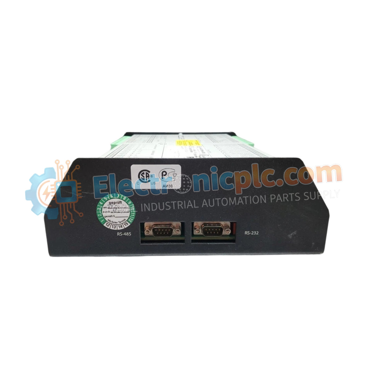
تم تكوين WOODWARD 8440-1878 (8440-1878 DSLC-2 Digital Synchronizer and Load Control) للمزامنة بتردد الانزلاق، ومطابقة الجهد، وتحيز السرعة في شبكات المولدات المتعددة، ويوفر تنفيذًا ماديًا/كهربائيًا مباشرًا.
| المعلمة | المواصفات |
|---|---|
| النموذج | 8440-1878 |
| العلامة التجارية | WOODWARD |
| المنشأ | الولايات المتحدة الأمريكية |
| الوزن | 1.34 كجم (2.95 رطل) |
| الأبعاد | 250 × 227 × 84 ملم (9.84 × 9.00 × 3.30 بوصة) |
| درجة حرارة التشغيل | -40 إلى 70 درجة مئوية |
| استهلاك الطاقة | 15 وات كحد أقصى |
| جهد الإدخال | 12 / 24 فولت تيار مستمر اسمي (نطاق تشغيل 8 إلى 40 فولت تيار مستمر) |
| تصنيف مدخل CT | 5 أمبير ثانوي |
| تصنيف جهد الناقل | 120 فولت تيار متردد / 480 فولت تيار متردد |
| جهد الإدخال/الإخراج الرقمي | مدخلات 12 / 24 فولت تيار مستمر ومخرجات مرحل |
| منافذ الاتصال | إيثرنت متكرر، واجهات تسلسلية متعددة |
يقوم منطق المعالجة بأخذ عينات مستمرة لزاوية الطور، وسعة الجهد، وتغذية الارتداد لتيار المحول 5 أمبير عبر ناقلات المولدات ثلاثية الأطوار. من خلال حساب انحرافات تردد الانزلاق في الوقت الفعلي، يقوم الوحدة بإخراج إشارات انحياز السرعة والجهد الديناميكية مباشرة إلى حلقة التحكم في السرعة. وهذا يحافظ على استجابة تغذية الارتداد عالية لحلقة المشغل أثناء تسلسل إغلاق القواطع الأوتوماتيكية، مما يمنع رحلات الطاقة العكسية العابرة وإجهاد العمود الميكانيكي.
س: كيف يتعامل مصدر الطاقة مع التقلبات قصيرة المدى في الجهد أثناء تشغيل المحرك؟
ج: يتيح نطاق إدخال التيار المستمر الواسع من 8 إلى 40 فولت تيار مستمر التشغيل المستمر أثناء انخفاض جهد البطارية إلى 8 فولت تيار مستمر دون إعادة ضبط المعالج أو مقاطعة بيانات مزامنة الشبكة.
س: ما هي الاحتياطات الواجب اتخاذها عند توصيل حلقات التيار الثانوي للمحول CT 5 أمبير؟
ج: يجب أن تظل جميع توصيلات CT الثانوية موصولة بإحكام بأطراف ذات معاوقة منخفضة. يؤدي الدائرة المفتوحة للتيار الثانوي للمحول CT 5 أمبير إلى حدوث ارتفاعات جهد حثية عالية يمكن أن تدمر دائرة قياس الإدخال.


