انتقل إلى معلومات المنتج
1 ل 3

A1BA4D-05 YOKOGAWA Terminal Board | New & Original Stock

A1BA4D-05 YOKOGAWA Terminal Board | New & Original Stock

Designed for robust signal distribution within Field Control Station (FIO) architectures, the YOKOGAWA A1BA4D-05 (A1BA4D-05) provides a reliable, DIN-rail mountable interface between field instrumentation and the DCS I/O modules. This...

21 يشاهد الناس هذا الآن

التوافرالكمية المتبقية: 99

رمز المنتج: A1BA4D-05
بائع: Yokogawa
فئة: Terminal Board
Related Series:

الشحن والإرجاع

توصيل موثوق به في جميع أنحاء العالم

  • شركات الشحن: يتم الشحن عبر DHL أو FedEx أو UPS أو USPS .
  • الشحن: تتم معالجة الطلبات خلال يوم عمل واحد إلى يومين، ويتم شحنها خلال 3 إلى 5 أيام عمل .
  • التتبع: يتم توفير تفاصيل التتبع الكاملة عبر البريد الإلكتروني عند الشحن.

ضمان استرداد الأموال خلال 30 يومًا

  • الضمان: فترة إرجاع لمدة 30 يومًا للمنتجات المتوفرة في المخزون والمغلفة من المصنع.
  • الشروط: يجب أن تكون المنتجات غير مفتوحة وغير مستخدمة وفي عبوتها الأصلية.
  • الأصالة: نضمن أن تكون الأجهزة أصلية 100% .

هل تحتاج إلى مزيد من التفاصيل؟ اقرأ سياسة الشحن وسياسة الاسترداد الكاملة.
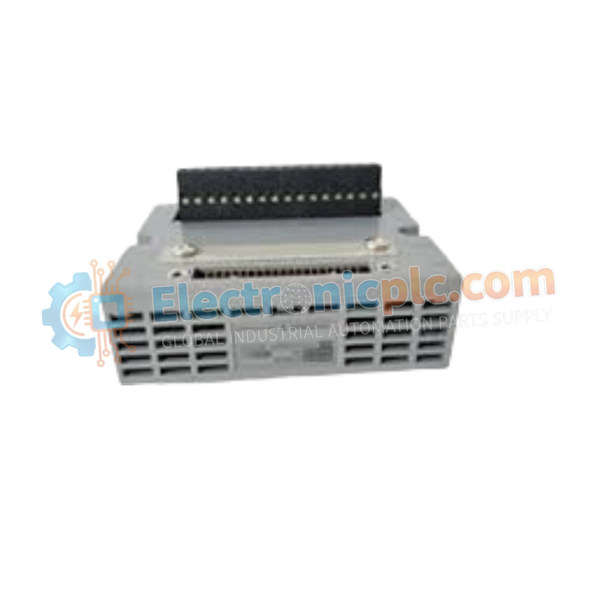
الأصالة والضمان

  • ضمان أصلي: نحن نوفر فقط قطع غيار أصلية 100%، جديدة تمامًا، ومغلقة من المصنع .
  • تغطية كاملة: كل مكون مدعوم بضمان شامل لمدة 12 شهرًا من تاريخ الشراء.
  • إمكانية التتبع: جميع المنتجات تأتي مع وثائق المصنع الأصلية والملحقات اللازمة للامتثال الكامل للمعايير الصناعية.

الدعم الفني والتوريد

  • مساعدة الخبراء: يقدم فريقنا الفني استشارات مجانية لمساعدتك في التحقق من التوافق مع أنظمة DCS و PLC.
  • مصادر القطع النادرة: متخصصون في المكونات القديمة والتي يصعب العثور عليها من Allen-Bradley و Siemens و ABB و HIMA وغيرها.
  • للاستفسارات المتعلقة بالكميات الكبيرة: تواصلوا معنا على pambo@5gplc.com للحصول على أسعار الكميات الكبيرة أو عروض أسعار المشاريع المخصصة.
عرض تفاصيل المنتج الكاملة

Designed for robust signal distribution within Field Control Station (FIO) architectures, the YOKOGAWA A1BA4D-05 (A1BA4D-05) provides a reliable, DIN-rail mountable interface between field instrumentation and the DCS I/O modules. This terminal board is engineered to manage analog signal connectivity for high-density I/O clusters, supporting both single and dual-redundant configurations.

Suffix Breakdown & Model Matrix

  • A1BA4D: Base model identifier for the Analog Terminal Board (DIN rail mount).
  • -0: Standard configuration identifier.
  • 5: Denotes the basic hardware type with no integrated explosion-proof protection.

Hardware Specifications

Parameter Specification
Model A1BA4D-05
Brand Yokogawa
Origin Subject to manufacturing batch
Weight 0.3 kg
Mounting Type DIN rail mount
Channels 16-channel x 1 or 8-channel x 1
Configuration Single and dual-redundant supported
Function Analog signal termination

Process Control Signal Connectivity

The A1BA4D-05 ensures signal integrity by providing a structured, low-impedance termination point for field wiring. Its modular design allows for rapid installation and maintenance within FIO cabinets, facilitating the transition of field signals—such as 4-20 mA loops or voltage inputs—into the control system. By accommodating both single and dual-redundant cabling, the board supports high-availability process loops where failure of a single path must not compromise control or monitoring functionality.

Frequently Asked Questions

Q: Does the A1BA4D-05 require specific tools for wiring?

A: The board utilizes standard screw-type terminals. Ensure the use of calibrated screwdrivers and appropriate wire ferrules to maintain secure connections that can withstand industrial vibration.

Q: Is this board compatible with both 8-channel and 16-channel modules?

A: Yes, the board is designed to interface with specified FIO analog modules that support either 8-channel or 16-channel densities, provided the internal jumper or configuration settings match the specific module requirements.

Field Installation Guidelines

  • Secure the DIN rail firmly to the backplane of the control cabinet, ensuring it provides a clean electrical path to the cabinet's grounding bus.
  • Strip field wiring to the specified length to ensure maximum contact surface within the terminals without exposing excessive bare conductor.
  • Maintain rigorous segregation between analog signal wiring and high-current power cables to prevent electromagnetic interference (EMI) that can degrade measurement accuracy.
  • Utilize identifying tags on both ends of the field cables to facilitate troubleshooting and mapping back to the I/O module channels.
  • Once wired, conduct a point-to-point continuity test from the field device to the terminal board before confirming the loop status via the DCS engineering station.