سلة التسوق الخاصة بي
0 عنصرًا
قطع غيار أصلية للأتمتة | توصيل سريع عالمي | ضمان لمدة 12 شهرًا — [احصل على عرض سعر]

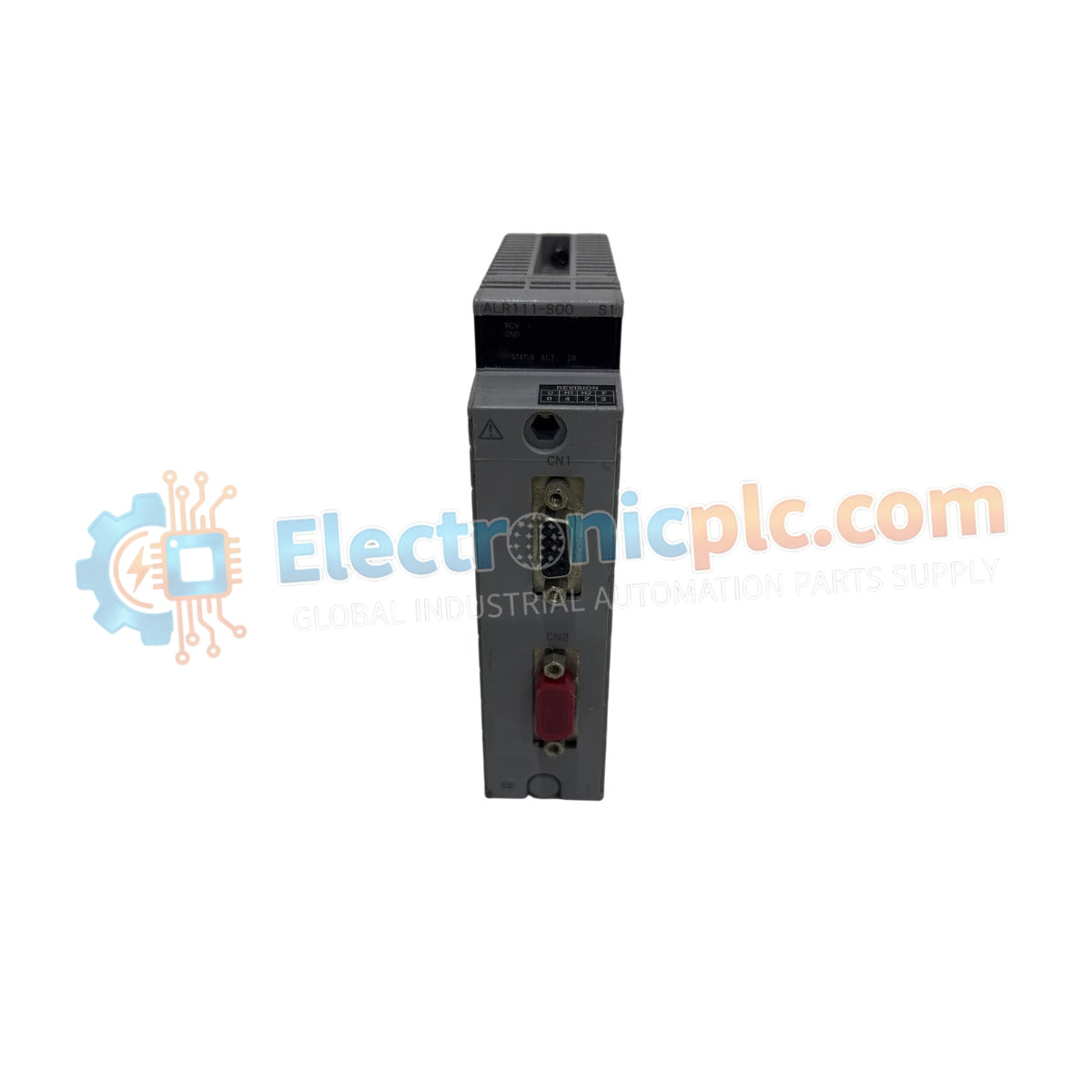
يعمل محول ناقل YOKOGAWA A2EE1A-T، والمفهرس أيضاً باسم A2EE1A-T ESB Bus Adapter، كمكون مادي مخصص لإنهاء الإشارة ومطابقة معاوقة الناقل ضمن أنظمة التحكم CENTUM VP.
| المعلمة | المواصفة |
|---|---|
| الموديل | A2EE1A-T |
| العلامة التجارية | YOKOGAWA |
| المنشأ | اليابان |
| الوزن | 0.3 كجم |
| الأبعاد | 2.2 × 12.4 × 12.6 سم |
| درجة حرارة التشغيل | النطاق الصناعي القياسي |
| استهلاك الطاقة | غير فعال (يعمل بالناقل) |
| توافق النظام | CENTUM VP, FIO Node, Optical ESB Bus Node |
| الوظيفة | إنهاء معاوقة ناقل ESB |
يحافظ محول A2EE1A-T على سلامة إشارة الشبكة من خلال توفير إنهاء نشط عند نهاية بنية ناقل ESB. تم تصميم الدائرة الداخلية خصيصًا للتخفيف من انعكاس الإشارة الذي يحدث في نهاية ناقل البيانات عالي السرعة، مما يضمن بقاء بيئة بروتوكول حلقة 4-20 مللي أمبير HART وحزم البيانات الرقمية دون انقطاع. يسهل المحول العزل الجلفاني داخل واجهة الناقل، مما يمنع انتشار ضوضاء الوضع المشترك بين وحدات التحكم الميدانية ووحدات العقد. يتطلب التطبيق الصحيح لهذه المقاومة النهائية للحفاظ على سرعة اتصال حتمية عبر منصات التحكم الموزعة، حيث أنها تثبت معاوقة خط الإرسال.
س: هل يلزم استخدام A2EE1A-T عند كل نقطة اتصال في ناقل ESB؟
ج: لا. تم تصميم A2EE1A-T للاستخدام خصيصًا في نهاية سلسلة ناقل ESB. سيؤدي التثبيت في النقاط الوسطية إلى تعطيل معاوقة الناقل وقد يتسبب في أخطاء اتصال.
س: هل يمكن استخدام هذا المحول لاستبدال موصلات كبل ESB القياسية؟
ج: لا. يؤدي A2EE1A-T وظيفة محددة لإنهاء الناقل ولا يوفر اتصالاً مباشرًا لكابلات التوصيل المتسلسل القياسية. يجب تثبيته عند نقطة اتصال العقدة النهائية.