سلة التسوق الخاصة بي
0 عنصرًا
قطع غيار أصلية للأتمتة | توصيل سريع عالمي | ضمان لمدة 12 شهرًا — [احصل على عرض سعر]

The YOKOGAWA AAI141-H00/K4A00 is a 16-channel, non-isolated analog input module engineered for integration within Yokogawa Distributed Control Systems (DCS). It is specifically designed to process 4-20 mA current signals while...
التوافر: الكمية المتبقية: 99
توصيل موثوق به في جميع أنحاء العالم
ضمان استرداد الأموال خلال 30 يومًا
هل تحتاج إلى مزيد من التفاصيل؟ اقرأ سياسة الشحن وسياسة الاسترداد الكاملة.
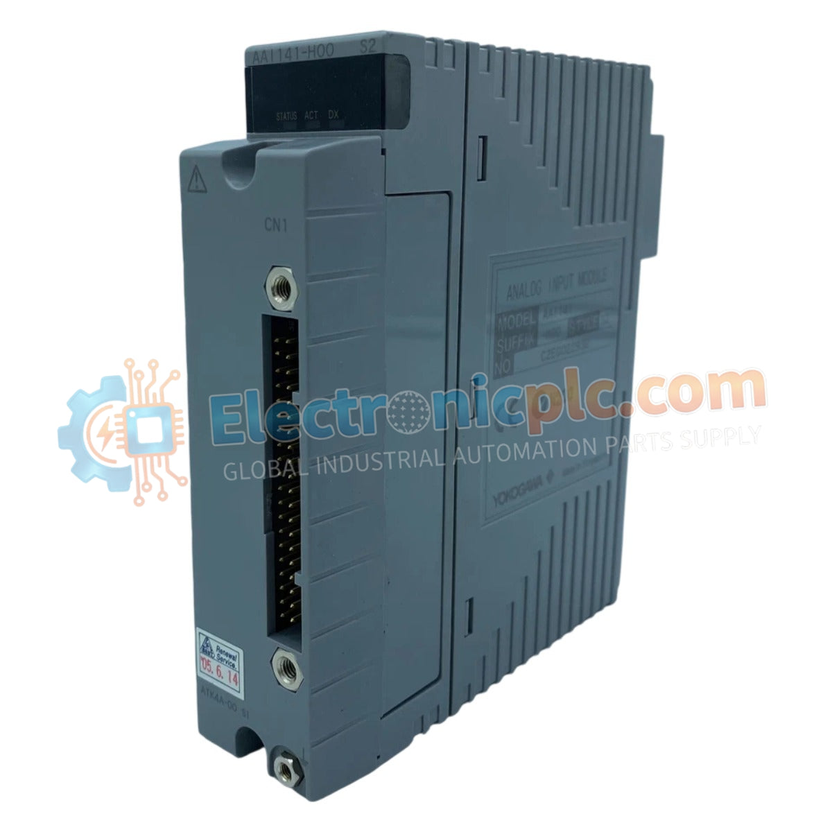
The YOKOGAWA AAI141-H00/K4A00 is a 16-channel, non-isolated analog input module engineered for integration within Yokogawa Distributed Control Systems (DCS). It is specifically designed to process 4-20 mA current signals while providing HART communication capabilities for advanced digital interaction with smart field devices.
| Parameter | Specification |
|---|---|
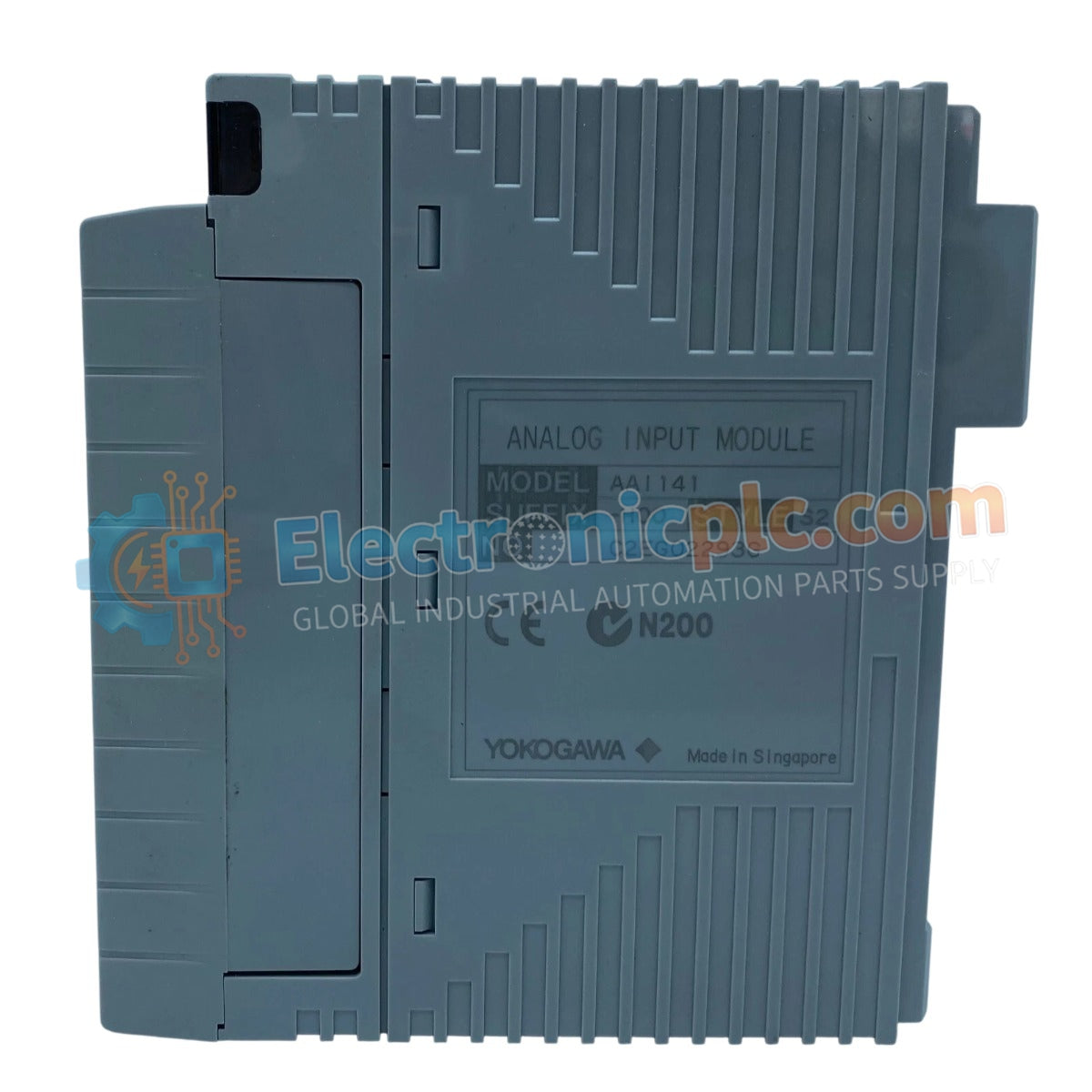
| Model | AAI141-H00/K4A00 |
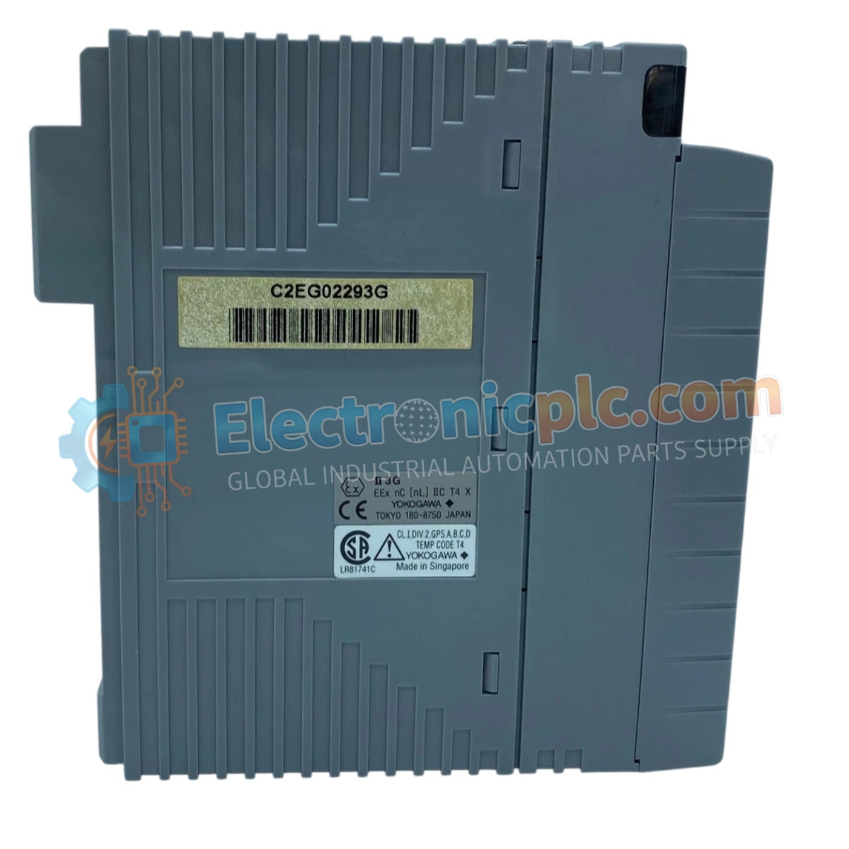
| Brand | YOKOGAWA |
| Channels | 16 (Non-isolated) |
| Input Range | 4-20 mA (up to 25 mA permissible) |
| Input Impedance (ON) | 250 Ω |
| Accuracy | ±16 µA (for 1 to 23 mA range) |
| Data Update Period | 40 ms |
| Power Supply (5V System) | 310 mA |
| Power Supply (24V System) | 450 mA |
| Withstand Voltage | 1.5 kV AC for 1 minute |
The AAI141-H00/K4A00 module facilitates high-density signal acquisition for process monitoring. By supporting the HART protocol, the module enables the DCS to extract secondary diagnostic variables from intelligent transmitters, reducing the need for additional wiring or standalone configuration tools. The inclusion of the ATK4A-00 KS Cable Interface Adapter simplifies the connection between the module and terminal boards, streamlining the installation process in complex industrial cabinets.
Q: Is this module isolated?
A: No, the AAI141-H00/K4A00 is a non-isolated analog input module. Ensure proper grounding and signal conditioning are addressed in your cabinet design to prevent ground loops.
Q: What are the transmitter power supply requirements?
A: The module provides transmitter power with a minimum output of 16.15 V at 20 mA and a maximum of 26.4 V at 0 mA.


