سلة التسوق الخاصة بي
0 عنصرًا
قطع غيار أصلية للأتمتة | توصيل سريع عالمي | ضمان لمدة 12 شهرًا — [احصل على عرض سعر]

Configured for precision signal conversion in process control networks, the YOKOGAWA AAI543-S00/A4S00 (AAI543-S00 Analog Output Module) provides direct physical electrical execution for actuator positioning and field device modulation.
التوافر: الكمية المتبقية: 99
توصيل موثوق به في جميع أنحاء العالم
ضمان استرداد الأموال خلال 30 يومًا
هل تحتاج إلى مزيد من التفاصيل؟ اقرأ سياسة الشحن وسياسة الاسترداد الكاملة.

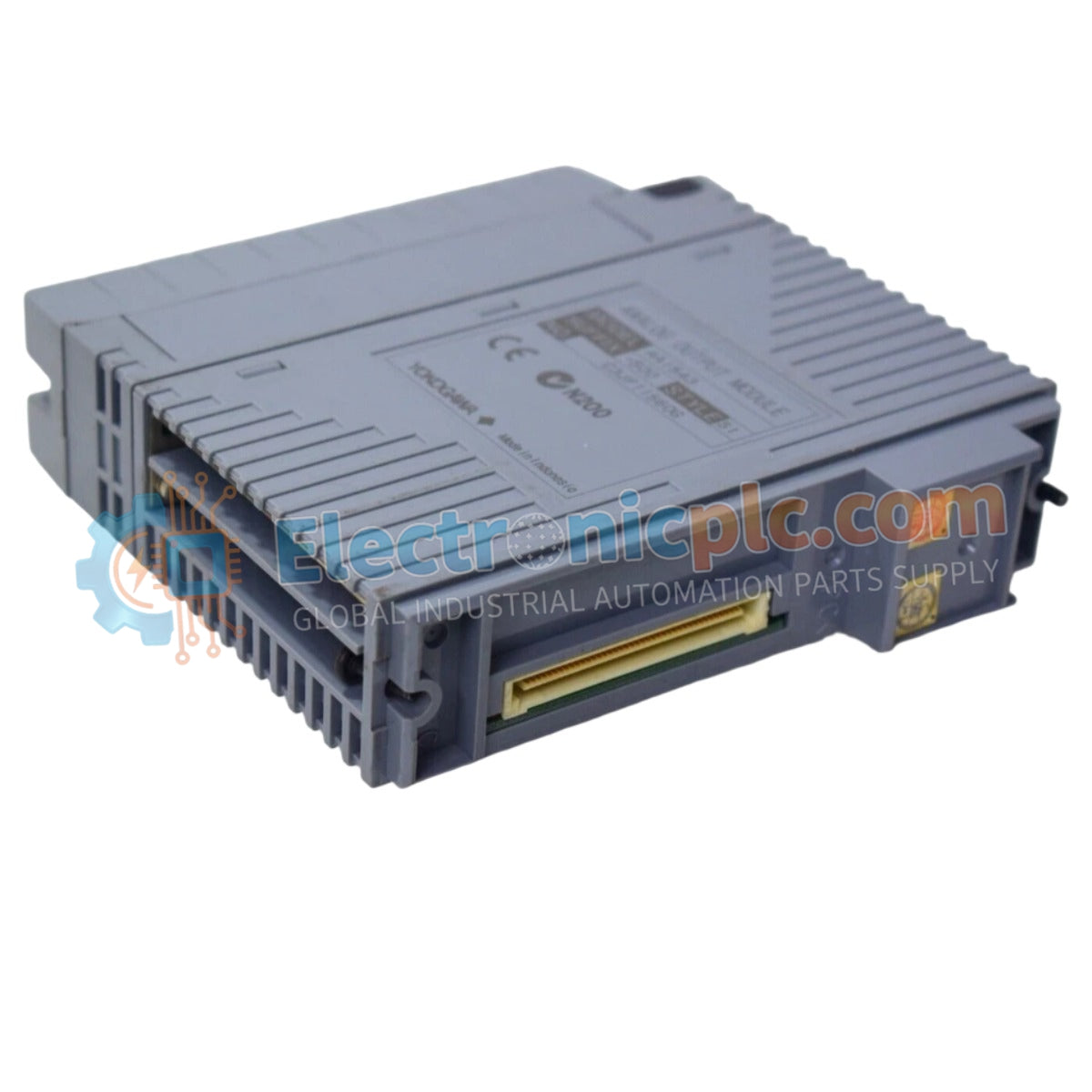
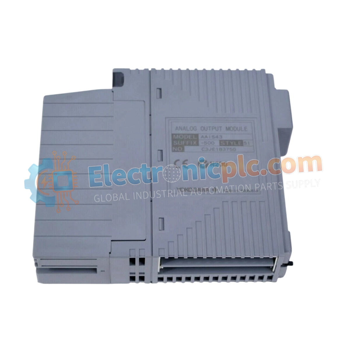
Configured for precision signal conversion in process control networks, the YOKOGAWA AAI543-S00/A4S00 (AAI543-S00 Analog Output Module) provides direct physical electrical execution for actuator positioning and field device modulation.
| Parameter | Specification |
|---|---|
| Model | AAI543-S00/A4S00 |
| Brand | YOKOGAWA |
| Origin | N/A |
| Weight | 0.3 kg |
| Dimensions | 16 cm x 10 cm x 3 cm |
| Operating Temp | -20 to 70 deg C |
| Output Channels | 16 isolated |
| Output Signal | 4 to 20 mA |
The AAI543-S00/A4S00 module utilizes channel-to-channel isolation to prevent ground loop interference within the DCS instrumentation architecture. It is engineered to maintain high-accuracy output signal delivery, supporting 4-20 mA HART loop protocol integration for seamless communication with intelligent field instruments. The internal circuitry is optimized to suppress signal noise, ensuring that control output remains stable under electromagnetic conditions common in process environments. The module supports both standard and fast switch-over response times in redundant configurations to maintain process control continuity.
Q: Does the AAI543-S00/A4S00 support redundant system configurations?
A: Yes. The module supports both standard and fast switch-over response configurations, allowing for integration into dual-redundant setups to enhance system availability.
Q: Is this module compatible with hazardous area installations?
A: The module is available with options for explosion protection; verify the specific part number requirements against your facility's hazardous area certification standards before deployment.


