سلة التسوق الخاصة بي
0 عنصرًا
قطع غيار أصلية للأتمتة | توصيل سريع عالمي | ضمان لمدة 12 شهرًا — [احصل على عرض سعر]

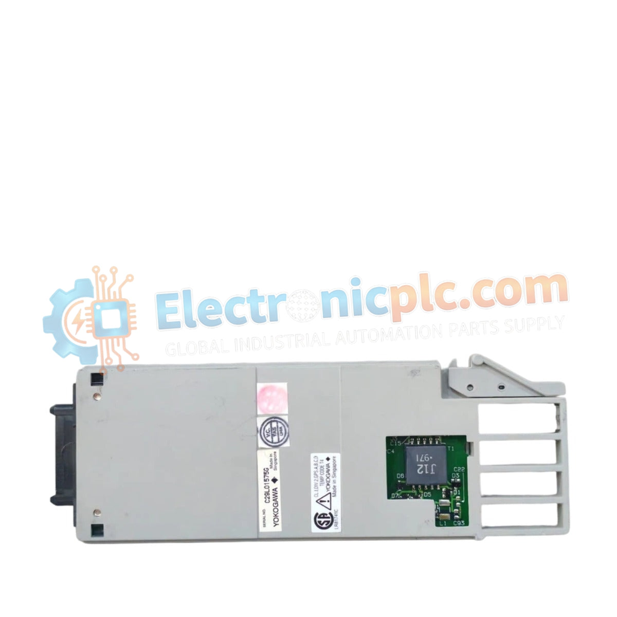
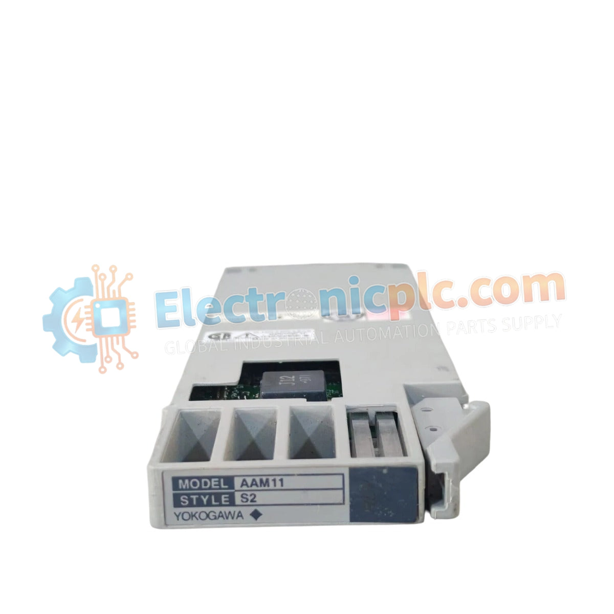
Configured for analog signal acquisition in control networks, the Yokogawa AAM11 S1 (AAM11 Current Voltage Input Module) provides direct physical/electrical execution of current and voltage loop processing.
التوافر: الكمية المتبقية: 99
توصيل موثوق به في جميع أنحاء العالم
ضمان استرداد الأموال خلال 30 يومًا
هل تحتاج إلى مزيد من التفاصيل؟ اقرأ سياسة الشحن وسياسة الاسترداد الكاملة.
Configured for analog signal acquisition in control networks, the Yokogawa AAM11 S1 (AAM11 Current Voltage Input Module) provides direct physical/electrical execution of current and voltage loop processing.
| Parameter | Specification |
|---|---|
| Model | AAM11 S1 |
| Brand | Yokogawa |
| Origin | Japan |
| Weight | 0.08 kg |
| Dimensions | 16.5 cm x 6 cm x 1 cm |
| Operating Temp | 0 to 50 deg C |
| Power Consumption | 150 mA at 24 VDC |
| Input Channels | Multi-channel configurable |
| Signal Input | Current/Voltage (Software selectable) |
The AAM11 S1 architecture facilitates integration with 4-20 mA HART loop protocol enabled instrumentation. To maintain signal integrity across long-run field cabling, the module incorporates channel-to-channel isolation, preventing ground potential differences from affecting the measurement accuracy. The design prioritizes stable common-mode rejection, ensuring that process variables remain within the defined conversion accuracy thresholds regardless of fluctuations in the field supply voltage.
Q: Does the AAM11 S1 require external loop power for 4-20 mA active transmitters?
A: The module supports both passive and active transmitter configurations; however, internal loop power provisioning is dependent on specific rack bus configuration settings.
Q: Is this module compatible with cold junction compensation (CJC) for thermocouple inputs?
A: This model is designed specifically for current and voltage signal processing and does not feature integrated CJC circuitry for direct thermocouple measurement.


