
سلة التسوق الخاصة بي
0 عنصرًا
قطع غيار أصلية للأتمتة | توصيل سريع عالمي | ضمان لمدة 12 شهرًا — [احصل على عرض سعر]

تم تكوين وحدة الإدخال YOKOGAWA AAP135-S50/13S00 (AAP135) للحصول على إشارة النبض عالية السرعة في منصات CENTUM CS 3000 وProSafe-RS، وهي توفر تنفيذًا ماديًا/كهربائيًا مباشرًا لقياس التدفق وعد النبض واكتشاف الأحداث. تعالج مكونات...
التوافر: في الأوراق المالية
توصيل موثوق به في جميع أنحاء العالم
ضمان استرداد الأموال خلال 30 يومًا
هل تحتاج إلى مزيد من التفاصيل؟ اقرأ سياسة الشحن وسياسة الاسترداد الكاملة.


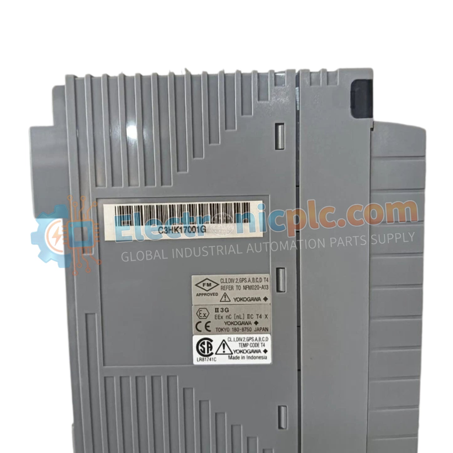
تم تكوين وحدة الإدخال YOKOGAWA AAP135-S50/13S00 (AAP135) للحصول على إشارة النبض عالية السرعة في منصات CENTUM CS 3000 وProSafe-RS، وهي توفر تنفيذًا ماديًا/كهربائيًا مباشرًا لقياس التدفق وعد النبض واكتشاف الأحداث. تعالج مكونات الأجهزة هذه إدخالات النبض لجهة الاتصال ON/OFF والجهد والتيار من خلال ثماني قنوات معزولة.
يمثل AAP135-S50/13S00 مراجعة أجهزة محددة ومحسّنة لبنى التحكم من Yokogawa:
AAP135: تسمية النموذج الأساسي لوحدة إدخال النبض ذات 8 قنوات.
S50: يحدد التكوين التشغيلي القياسي لتكامل نظام التحكم الموزع (DCS) ونظام السلامة الآلي (SIS).
13S00: يحدد الإصدار المحدد وترتيب موصل الطرف لتجميع الوحدة.
| المعلمة | المواصفات |
| النموذج | AAP135-S50/13S00 |
| الماركة | YOKOGAWA |
| المنشأ | اليابان |
| الوزن | 0.3 كجم |
| الأبعاد | غلاف وحدة قياسي |
| درجة حرارة التشغيل | -20 درجة مئوية إلى 70 درجة مئوية |
| استهلاك الطاقة | 5 فولت تيار مستمر (300 مللي أمبير)، 24 فولت تيار مستمر (400 مللي أمبير) |
| قنوات الإدخال | 8 (معزولة) |
| نطاق التردد | 0 إلى 10 كيلو هرتز |
| دورة تحديث البيانات | 2 مللي ثانية |
تحافظ وحدة AAP135 على سلامة الحلقة الصارمة للأجهزة الميدانية. وهي تدعم عزل قناة-قناة بجهد تحمل يبلغ 500 فولت تيار متردد، مما يضمن عدم انتشار الضوضاء الكهربائية ذات النمط المشترك بين القنوات أو إلى اللوحة الخلفية للنظام الداخلي. يعد هذا العزل أمرًا بالغ الأهمية للعد الدقيق للنبضات في البيئات الصناعية حيث توجد فروق محتملة للأرض أو عابرات عالية التردد.
س: هل يمكن استخدام AAP135-S50/13S00 مع أجهزة إرسال حقلية نشطة 24 فولت تيار مستمر؟
ج: نعم، توفر الوحدة مصدر طاقة داخلي لجهاز الإرسال بقوة 24 فولت تيار مستمر (حد أقصى 30 مللي أمبير) أو 12 فولت تيار مستمر (حد أقصى 40 مللي أمبير)، مما يتيح الاتصال المباشر بالعديد من أجهزة الاستشعار القياسية المثبتة في الحقل لتوليد النبضات.
س: هل مرشح منع الاهتزاز قابل للتعديل؟
ج: نعم، تتميز الوحدة بفلترة إشارة قابلة للتكوين. يمكن ضبط هذا المرشح عبر برامج النظام لقمع الارتداد أو الضوضاء على مدخلات الاتصال، مما يضمن تسجيل الانتقالات الصحيحة فقط بواسطة عداد النبضات.
تأكد من تأريض سطح التركيب وفقًا لمعيار المنشأة لتوفير مسار منخفض المعاوقة لتفريغ التداخل الكهرومغناطيسي/التردد اللاسلكي من غلاف الوحدة.
تحقق من صحة قطبية الأسلاك الميدانية لنوع الإدخال المحدد (الجهد أو التيار أو جهة الاتصال). قد تؤدي القطبية غير الصحيحة على المدخلات النبضية إلى أصفار في العدد أو عدم استقرار الإشارة.
استخدم الكابلات المزدوجة المجدولة المعزولة لجميع إشارات إدخال النبض لتقليل الاقتران الحثي من خطوط الجهد العالي القريبة. قم بإنهاء الدرع في قضيب تأريض الخزانة فقط.
عند استخدام مصدر الطاقة الداخلي لجهاز الإرسال، تحقق من أن تيار الحمل الكلي لا يتجاوز 40 مللي أمبير المحدد (لـ 12 فولت تيار مستمر) أو 30 مللي أمبير (لـ 24 فولت تيار مستمر) لكل قناة.
بعد التثبيت الفعلي، افحص وصلات طرف المسمار المعزولة للتأكد من إحكامها وتأكد من عدم وجود أي خيوط سلكية شاردة تتسبب في حدوث دوائر قصيرة بين الأطراف المتجاورة.


