سلة التسوق الخاصة بي
0 عنصرًا
قطع غيار أصلية للأتمتة | توصيل سريع عالمي | ضمان لمدة 12 شهرًا — [احصل على عرض سعر]

Configured for discrete signal acquisition in distributed control networks, the Yokogawa ADM11 S3 (ADM11 S3 Contact Input Module) provides direct physical monitoring of binary status inputs from field-side switches, pushbuttons,...
التوافر: الكمية المتبقية: 99
توصيل موثوق به في جميع أنحاء العالم
ضمان استرداد الأموال خلال 30 يومًا
هل تحتاج إلى مزيد من التفاصيل؟ اقرأ سياسة الشحن وسياسة الاسترداد الكاملة.

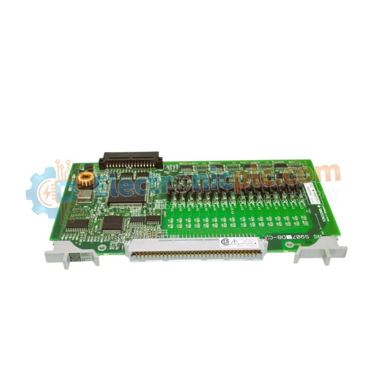
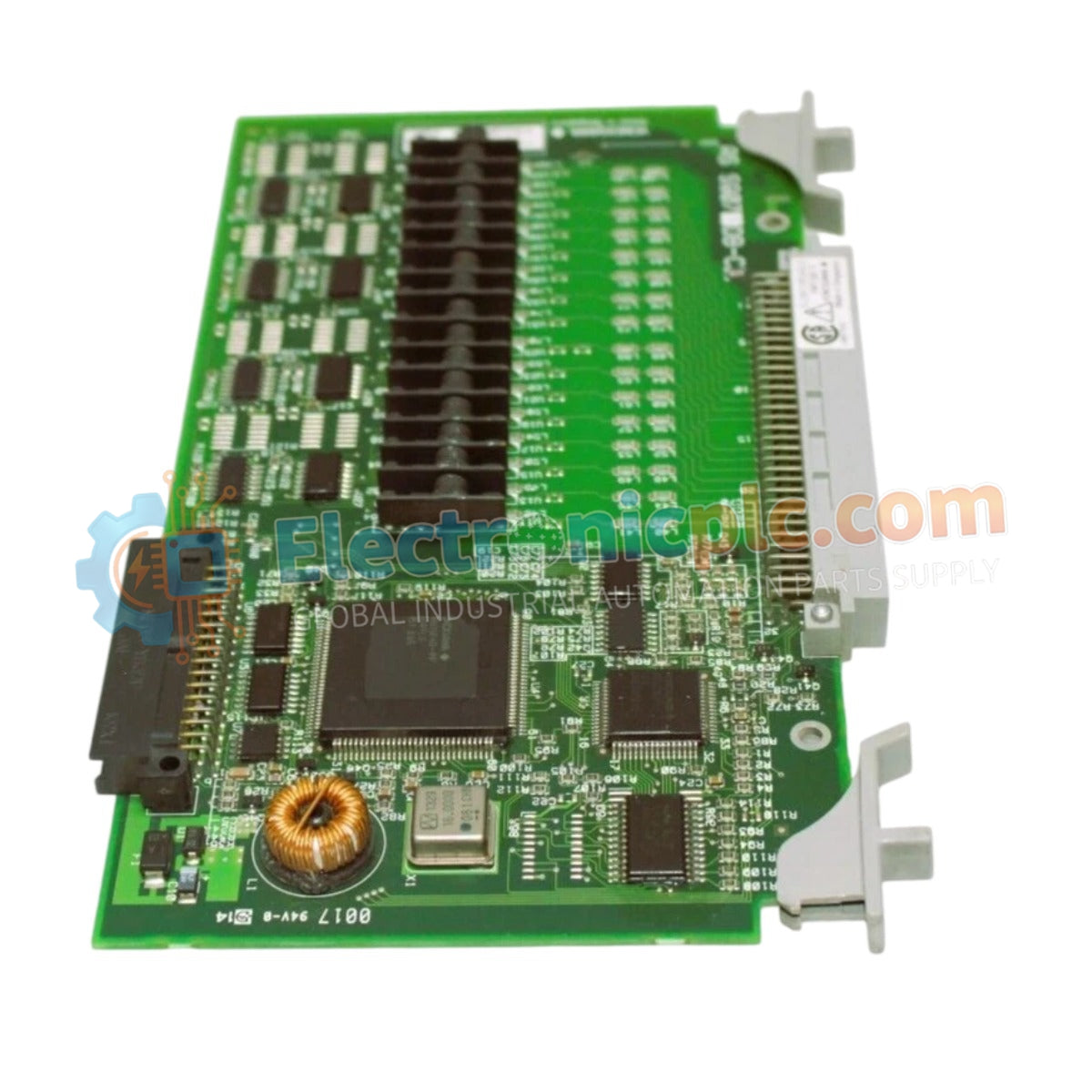
Configured for discrete signal acquisition in distributed control networks, the Yokogawa ADM11 S3 (ADM11 S3 Contact Input Module) provides direct physical monitoring of binary status inputs from field-side switches, pushbuttons, and sensors. This component serves as an interface for transferring real-time contact states into the CENTUM VP control architecture, utilizing internal logic to register transition events.
The ADM11 S3 model designation specifies a 16-channel hardware configuration designed for standard CENTUM VP input-processing applications. The "S3" suffix denotes the specific hardware revision compatible with standard DCS field-wiring requirements and cabinet mounting specifications.
| Parameter | Specification |
|---|---|
| Model | ADM11 S3 |
| Brand | Yokogawa |
| Origin | Japan |
| Weight | 0.29 kg |
| Dimensions | Standard DIN-rail module format |
| Operating Temp | 0 to 60 deg C |
| Power Consumption | Low-draw architecture |
| Input Channels | 16 |
| Input Voltage | 4 to 32 V DC |
| Humidity | 5 to 95 % RH (non-condensing) |
The ADM11 S3 utilizes galvanic isolation between each input channel to ensure total electrical decoupling between field circuits and the DCS backplane. This design prevents common-mode noise and ground potential differences from affecting the integrity of the 4-32 V DC input signals. By maintaining channel-to-channel isolation, the module preserves the stability of the CENTUM VP input loop, ensuring that localized field faults or wiring surges remain confined and do not propagate to the central processor or adjacent modules.
Q: Does the galvanic isolation feature eliminate the need for external surge protection devices?
A: Galvanic isolation protects against signal interference and ground loops; however, dedicated surge suppression should still be installed at the field termination level if the wiring exits the control cabinet or encounters high-EMI environments.
Q: Can this module operate effectively in environments with 90 % relative humidity?
A: Yes, provided the conditions are non-condensing. High-humidity environments require verified cabinet climate control to prevent moisture-induced tracking on the terminal blocks or backplane connectors.


