سلة التسوق الخاصة بي
0 عنصرًا
قطع غيار أصلية للأتمتة | توصيل سريع عالمي | ضمان لمدة 12 شهرًا — [احصل على عرض سعر]

Configured for precise discrete signal acquisition, the Yokogawa ADM12C S2 (ADM12C Digital Input Module) facilitates the monitoring of field-side industrial status indicators within Yokogawa automation architectures, supporting stable data integration...
التوافر: الكمية المتبقية: 99
توصيل موثوق به في جميع أنحاء العالم
ضمان استرداد الأموال خلال 30 يومًا
هل تحتاج إلى مزيد من التفاصيل؟ اقرأ سياسة الشحن وسياسة الاسترداد الكاملة.
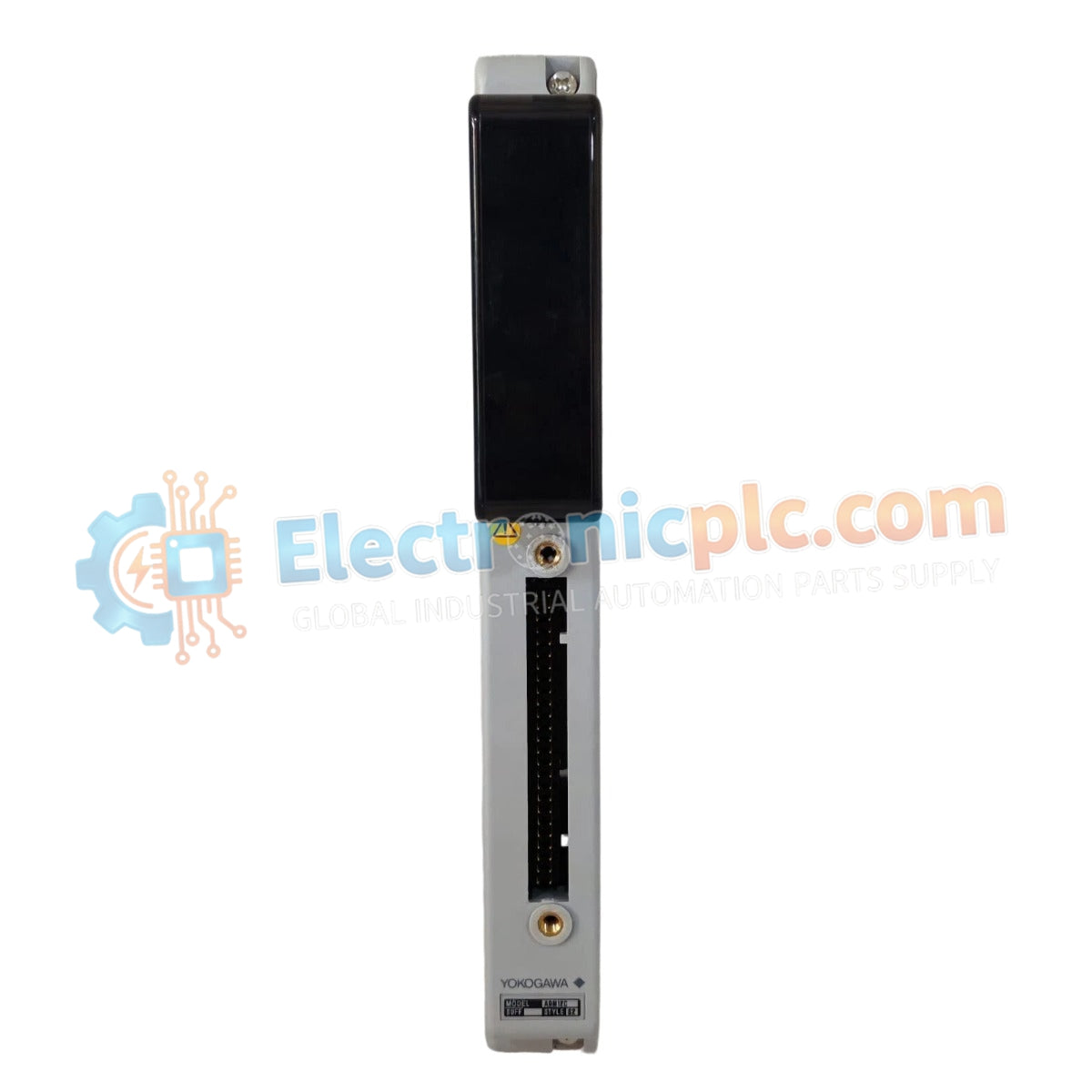

Configured for precise discrete signal acquisition, the Yokogawa ADM12C S2 (ADM12C Digital Input Module) facilitates the monitoring of field-side industrial status indicators within Yokogawa automation architectures, supporting stable data integration via the Modbus RTU communication protocol.
| Parameter | Specification |
|---|---|
| Model | ADM12C S2 |
| Brand | Yokogawa |
| Type | Digital Input Module |
| Input Channels | 12 channels |
| Operating Voltage | 24 VDC |
| Input Current | ≤ 20 mA |
| Protocol | Modbus RTU |
| Dimensions | 82 mm x 82 mm x 35 mm |
| Weight | 0.14 kg (0.31 lbs) |
| Operating Temp | -10 to +55 deg C |
The ADM12C S2 functions as a high-reliability interface that captures discrete states from field sensors and switches. By utilizing the Modbus RTU protocol, the module provides a standard communication path for real-time status updates, ensuring that control systems receive accurate and low-latency input data. This capability is critical for environments requiring consistent monitoring of interlocking safety switches, equipment running status, and process alarm conditions.
Q: Is the ADM12C S2 compatible with non-Modbus industrial controllers?
A: The module is primarily engineered for Modbus RTU communication; while other protocols may be implemented through external gateways, direct integration requires a controller capable of acting as a Modbus Master.
Q: Can the input voltage be adjusted for higher sensitivity?
A: The module is fixed for a 24 VDC nominal input; altering the voltage level outside of the rated specifications will impact the internal opto-isolator trigger thresholds and may lead to module failure.


