سلة التسوق الخاصة بي
0 عنصرًا
قطع غيار أصلية للأتمتة | توصيل سريع عالمي | ضمان لمدة 12 شهرًا — [احصل على عرض سعر]

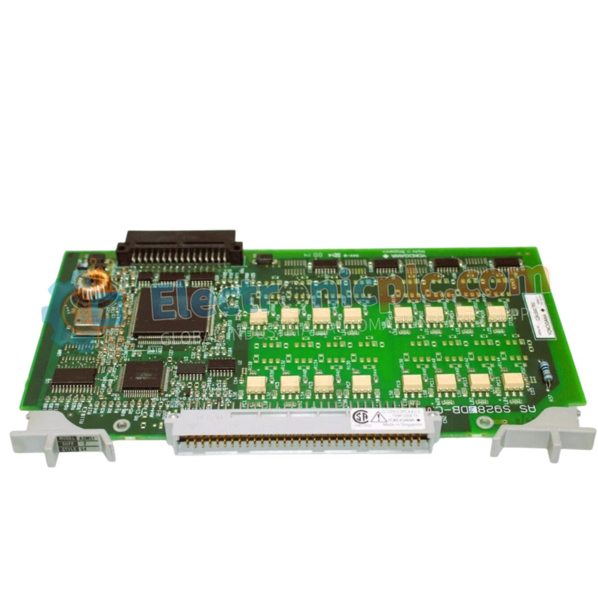
Configured for precision signal acquisition in process control platforms, the Yokogawa ADM52C-2/CE1 (ADM52C Analog Input Module) provides direct physical/electrical execution of 8-channel voltage and current signal conversion.
التوافر: في الأوراق المالية
توصيل موثوق به في جميع أنحاء العالم
ضمان استرداد الأموال خلال 30 يومًا
هل تحتاج إلى مزيد من التفاصيل؟ اقرأ سياسة الشحن وسياسة الاسترداد الكاملة.


Configured for precision signal acquisition in process control platforms, the Yokogawa ADM52C-2/CE1 (ADM52C Analog Input Module) provides direct physical/electrical execution of 8-channel voltage and current signal conversion.
| Parameter | Specification |
|---|---|
| Model | ADM52C-2/CE1 |
| Brand | Yokogawa |
| Origin | Japan |
| Weight | 0.5 kg |
| Dimensions | 130 mm x 90 mm x 100 mm |
| Operating Temp | -20 deg C to 60 deg C |
| Power Consumption | 5 W |
| Input Channels | 8 analog |
| Input Impedance | 250 Ohm (Current) / 10 MOhm (Voltage) |
| Accuracy | +/- 0.1% (Current) / +/- 0.2% (Voltage) |
| Sampling Rate | 100 ms per channel |
The ADM52C-2/CE1 utilizes isolated current inputs to mitigate the impact of ground potential differences across the process control loop. Integration within DCS racks requires adherence to standard impedance matching; current loops are terminated via a 250 Ohm burden resistor to satisfy 4-20 mA HART loop protocol requirements. Channel-to-channel isolation is maintained to prevent common-mode voltage transfer between sensors. Users should monitor signal integrity when deploying 0-10 V inputs, as the 10 MOhm high-impedance state makes these channels susceptible to induced noise from nearby high-frequency power cabling.
Q: Can the 24 VDC power input fluctuate without affecting measurement precision?
A: The module is rated for 24 VDC +/- 20%. Excursions outside this range may introduce nonlinearity in the 16-bit A/D conversion process, potentially exceeding the specified +/- 0.1% or +/- 0.2% accuracy thresholds.
Q: Are the current and voltage inputs hot-swappable during active system control?
A: The module is not designed for hot-swapping. Before physical removal or insertion into the DIN rail or panel, verify that the local rack power has been de-energized to prevent arcing at the backplane interface.


