
سلة التسوق الخاصة بي
0 عنصرًا
قطع غيار أصلية للأتمتة | توصيل سريع عالمي | ضمان لمدة 12 شهرًا — [احصل على عرض سعر]

تم تكوين YOKOGAWA AED5D-01 (لوحة طرفية AED5D) لإنهاء الإشارة التناظرية في معماريات التحكم CENTUM VP، ويوفر تنفيذًا ماديًا/كهربائيًا مباشرًا لربط الأجهزة الميدانية. تعالج هذه المكونة 16 قناة إدخال/إخراج عبر أطراف...
التوافر: في الأوراق المالية
توصيل موثوق به في جميع أنحاء العالم
ضمان استرداد الأموال خلال 30 يومًا
هل تحتاج إلى مزيد من التفاصيل؟ اقرأ سياسة الشحن وسياسة الاسترداد الكاملة.


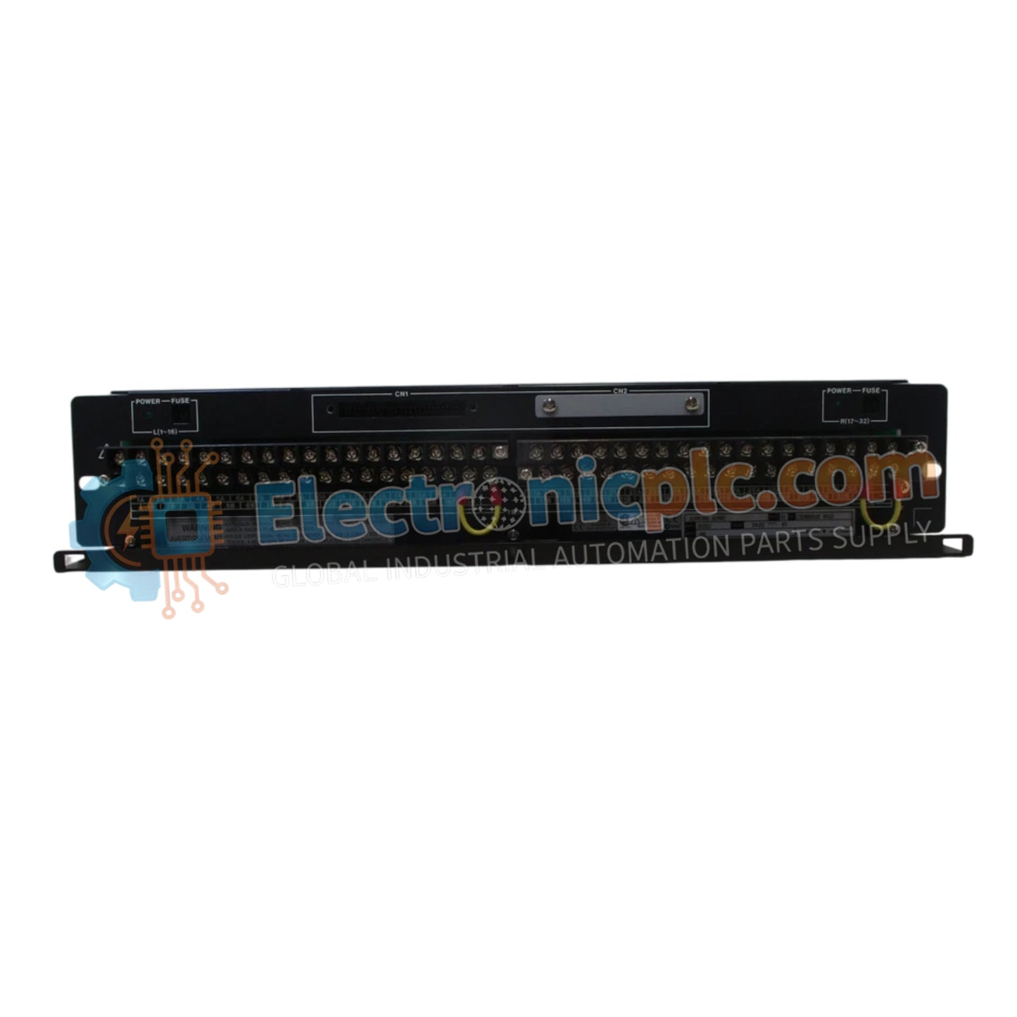
تم تكوين YOKOGAWA AED5D-01 (لوحة طرفية AED5D) لإنهاء الإشارة التناظرية في معماريات التحكم CENTUM VP، ويوفر تنفيذًا ماديًا/كهربائيًا مباشرًا لربط الأجهزة الميدانية. تعالج هذه المكونة 16 قناة إدخال/إخراج عبر أطراف برغي M4 آمنة، وتعمل كجسر وصل بين الأسلاك الميدانية وكابلات KS1 على جانب النظام.
| المعلمة | المواصفات |
| الموديل | AED5D-01 |
| العلامة التجارية | YOKOGAWA |
| المنشأ | اليابان |
| الوزن | 1.5 كجم |
| الأبعاد | 482.6 مم × 465.1 مم × 440 مم |
| درجة حرارة التشغيل | المعيار الصناعي |
| تصنيف الطاقة | 4 أمبير، 24 فولت تيار مستمر |
| قنوات الإدخال/الإخراج | 16 |
| نوع الطرف | برغي M4 |
تم تصميم AED5D-01 للحفاظ على سلامة الحلقة العالية ضمن شبكات التحكم الموزعة. وهو يدعم إرسال إشارة بروتوكول حلقة HART 4-20 مللي أمبير عبر مسارات نحاسية عالية التوصيل، مما يضمن أدنى مقاومة للتلامس. تتضمن اللوحة ممتصات اندفاع مدمجة لقمع الفولتية العابرة، وحماية بطاقات إدخال DCS الحساسة من الاندفاعات الكهربائية الشائعة في الكابلات الميدانية لمسافات طويلة. يتم التحقق من العزل الجلفاني وقوة العزل الكهربائي حتى 500 فولت تيار متردد لمدة دقيقة واحدة، مما يمنع التداخل عبر القنوات.
س: هل يوفر AED5D-01 حواجز أمان جوهري (Ex i) للمواقع الخطرة؟
ج: لا، AED5D-01 هي لوحة طرفية قياسية ولا تتضمن حواجز أمان جوهري. وهي مصممة للاستخدام في البيئات غير الخطرة أو تتطلب حواجز خارجية إذا كانت متصلة بأجهزة ميدانية في المناطق المتفجرة.
س: هل يمكن تبديل كابل KS1 على الساخن بينما تكون الأجهزة الميدانية مزودة بالطاقة؟
ج: بينما واجهة KS1 قوية، يوصى بعزل الطاقة عن الحلقة قبل توصيل الكابل أو فصله لمنع العابر الكهربائي من التأثير على وحدة إدخال/إخراج DCS أو جهاز الإرسال الميداني.
تأكد من تأريض الرف مقاس 19 بوصة إلى قضيب تأريض الخزانة الرئيسي للحفاظ على مرجع فعال لدائرة حماية الاندفاع.
قم بإنهاء جميع الأسلاك الميدانية باستخدام أطراف M4 من النوع الحلقي. تأكد من إحكام ربط البراغي بالعزم المحدد من قبل الشركة المصنعة لمنع توصيلات عالية المقاومة أو انخفاضات إشارة متقطعة.
قم بتوجيه الأسلاك الميدانية وكابل إشارة KS1 في صواني أو قنوات منفصلة لتجنب الحث من كابلات التيار المتردد عالية الجهد، مما قد يقلل من دقة الإشارة التناظرية.
تحقق من مقاومة العزل عبر الأطراف بشكل دوري؛ يجب أن تظل القراءات أعلى من 100 ميجا أوم عند 500 فولت تيار مستمر لضمان موثوقية طويلة الأجل.
في البيئات ذات الاهتزازات العالية، استخدم مركب قفل الخيط (غير موصل) على براغي طرف M4 أو قم بإجراء عمليات فحص دورية للشد لضمان سلامة الاتصال.


