سلة التسوق الخاصة بي
0 عنصرًا
قطع غيار أصلية للأتمتة | توصيل سريع عالمي | ضمان لمدة 12 شهرًا — [احصل على عرض سعر]

Configured for optical network extension in CENTUM VP systems, the Yokogawa AIP571 (AIP571 Electrical Transceiver RIO I/O Module) provides direct physical execution of high-speed data transmission between Remote I/O nodes...
التوافر: الكمية المتبقية: 99
توصيل موثوق به في جميع أنحاء العالم
ضمان استرداد الأموال خلال 30 يومًا
هل تحتاج إلى مزيد من التفاصيل؟ اقرأ سياسة الشحن وسياسة الاسترداد الكاملة.


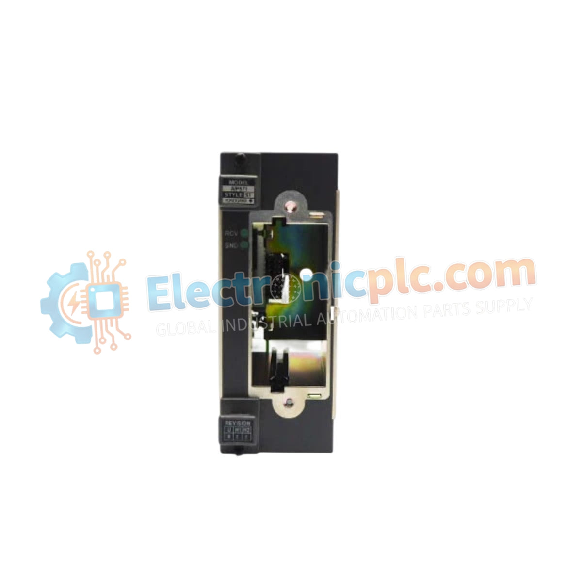
Configured for optical network extension in CENTUM VP systems, the Yokogawa AIP571 (AIP571 Electrical Transceiver RIO I/O Module) provides direct physical execution of high-speed data transmission between Remote I/O nodes and the Field Control Unit (FCU) via fiber-optic media.
| Parameter | Specification |
|---|---|
| Model | AIP571 |
| Brand | Yokogawa |
| Origin | Japan |
| Weight | 0.5 kg |
| Dimensions | 160 mm x 60 mm x 30 mm |
| Operating Temp | -20 deg C to 70 deg C |
| Power Consumption | 24 VDC / 20 W |
| Transmission Speed | Up to 100 Mbps |
| Communication Medium | Optical fiber cable |
The AIP571 module acts as a high-bandwidth optical-to-electrical interface, maintaining channel-to-channel isolation to prevent electrical transients from propagating between the control bus and remote field segments. The module supports redundant communication paths, executing sub-millisecond failover logic to ensure continuous data flow. By utilizing optical fiber transmission, the unit eliminates electromagnetic interference (EMI) and provides ground loop immunity, ensuring that FOUNDATION Fieldbus and HART protocol packets remain within strict timing tolerances required by the CENTUM VP control cycle.
Q: Can the AIP571 be used to establish redundant communication links?
A: Yes, the module is specifically engineered to support dual, redundant communication paths. In the event of a primary fiber-optic link failure, the AIP571 automatically switches traffic to the secondary path to maintain system availability.
Q: What precautions should be taken when handling the optical interface?
A: Ensure that optical connectors are cleaned with industry-standard fiber inspection and cleaning tools prior to mating. Contamination on the optical transceiver face can lead to high attenuation, signal instability, or complete communication failure.


