سلة التسوق الخاصة بي
0 عنصرًا
قطع غيار أصلية للأتمتة | توصيل سريع عالمي | ضمان لمدة 12 شهرًا — [احصل على عرض سعر]

Configured for high-speed network integration in control systems, the YOKOGAWA AIP851-A310 (AIP851 V-NET Coupler Module) provides direct physical and electrical execution of V-NET communication tasks.
التوافر: الكمية المتبقية: 99
توصيل موثوق به في جميع أنحاء العالم
ضمان استرداد الأموال خلال 30 يومًا
هل تحتاج إلى مزيد من التفاصيل؟ اقرأ سياسة الشحن وسياسة الاسترداد الكاملة.

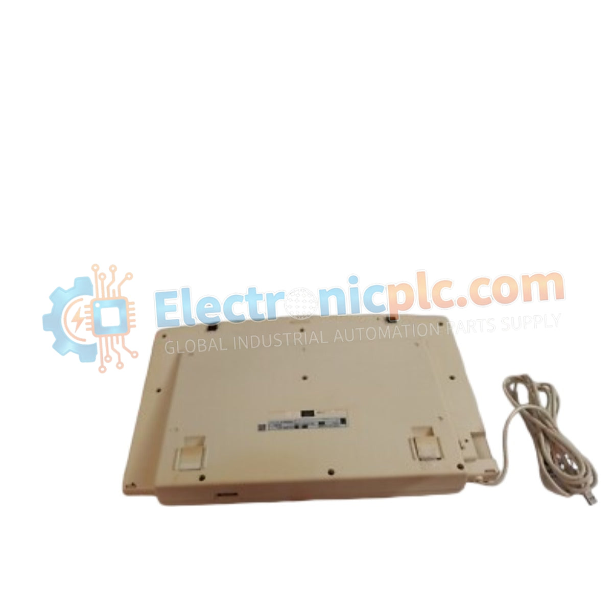
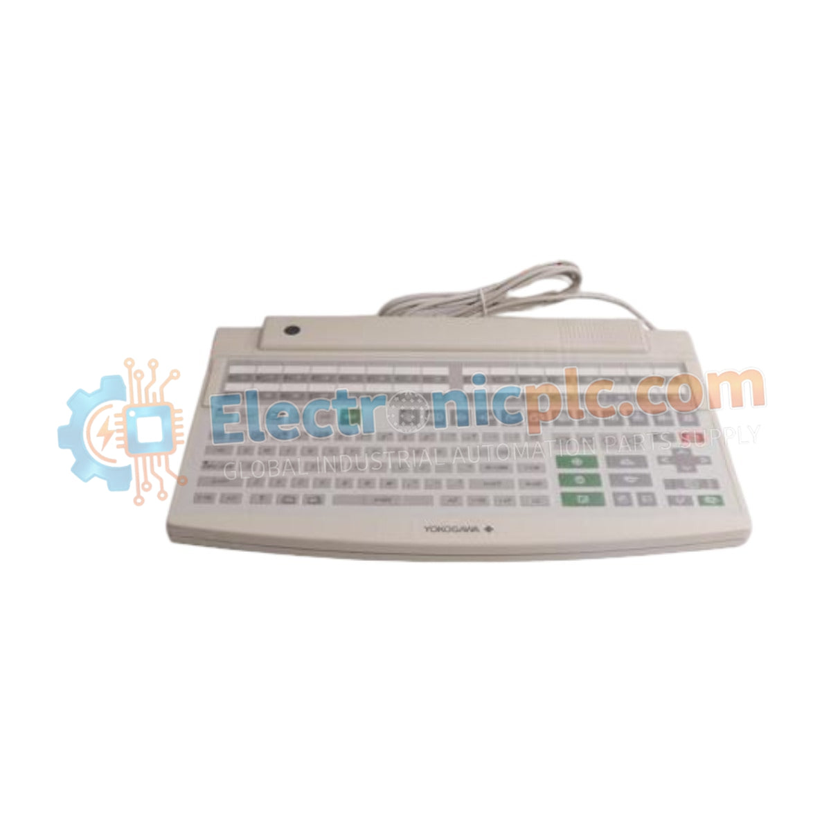
Configured for high-speed network integration in control systems, the YOKOGAWA AIP851-A310 (AIP851 V-NET Coupler Module) provides direct physical and electrical execution of V-NET communication tasks.
| Suffix Code | Description |
|---|---|
| AIP851 | Base Model (V-NET Coupler Module) |
| -A310 | Hardware revision and interface configuration code |
| Parameter | Specification |
|---|---|
| Model | AIP851-A310 |
| Brand | YOKOGAWA |
| Origin | janpan |
| Weight | 23 kg |
| Dimensions | 3.2 cm x 10.6 cm x 13 cm |
| Operating Temp | Not Specified |
| Power Consumption | Not Specified |
| Communication Interface | V-NET |
The AIP851 architecture incorporates channel-to-channel isolation to prevent ground loops and common-mode noise interference within the V-NET loop. This module ensures galvanic isolation between the internal control bus and the external network segments, maintaining signal integrity in high-EMI environments. Proper configuration of this coupler is required to ensure deterministic data transfer across the distributed control architecture, preventing packet collisions and communication latency within the network segment.
Q: Is the AIP851-A310 hot-swappable during normal system operation?
A: No, the module is not designed for hot-swapping. The V-NET bus power must be de-energized prior to installation or removal to avoid electrical damage to the backplane communication pins.
Q: What is the primary function of the V-NET coupling on this module?
A: The module serves as a bridge for the V-NET control network, managing signal levels and protocol timing to facilitate consistent data transmission between Field Control Stations and associated human interface units.


