سلة التسوق الخاصة بي
0 عنصرًا
قطع غيار أصلية للأتمتة | توصيل سريع عالمي | ضمان لمدة 12 شهرًا — [احصل على عرض سعر]

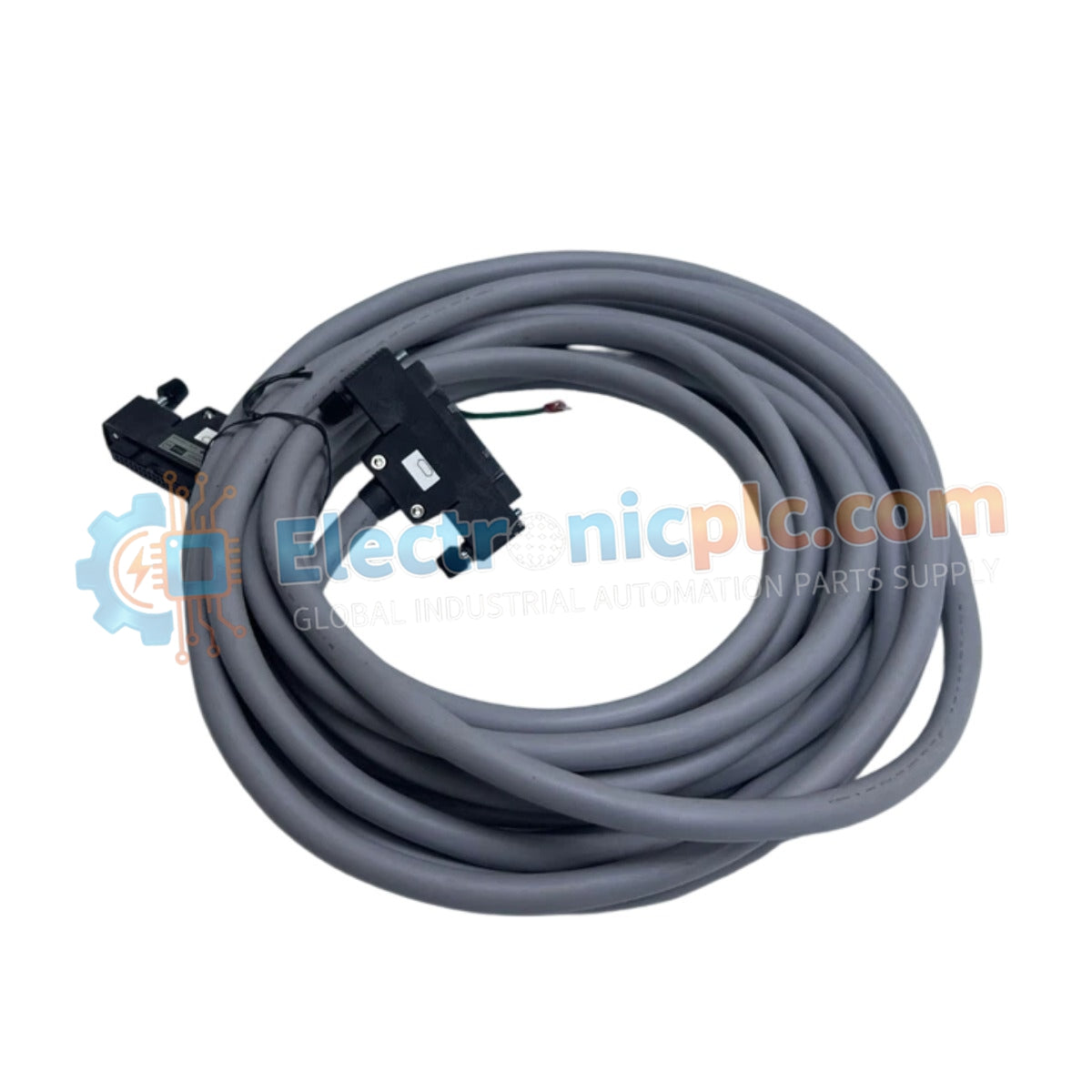
Configured for high-density signal interconnects within DCS and PLC control architectures, the YOKOGAWA AKB337-M015 (AKB337 Signal Cable) provides direct physical and electrical execution of multi-channel data transmission.
التوافر: الكمية المتبقية: 99
توصيل موثوق به في جميع أنحاء العالم
ضمان استرداد الأموال خلال 30 يومًا
هل تحتاج إلى مزيد من التفاصيل؟ اقرأ سياسة الشحن وسياسة الاسترداد الكاملة.


Configured for high-density signal interconnects within DCS and PLC control architectures, the YOKOGAWA AKB337-M015 (AKB337 Signal Cable) provides direct physical and electrical execution of multi-channel data transmission.
The AKB337 series utilizes standardized suffix codes to define physical length requirements for cabinet-to-cabinet or cabinet-to-field termination unit (FTU) routing:
| Parameter | Specification |
|---|---|
| Model | AKB337-M015 |
| Brand | YOKOGAWA |
| Origin | Japan |
| Weight | 2.5 kg |
| Dimensions | 15 meters length |
| Operating Temp | -20 deg C to +70 deg C |
| Power Consumption | Passive (Signal transmission) |
| Connector Type | 50-pin IDC to 50-pin IDC |
The AKB337 assembly utilizes a multi-conductor structure designed for low-latency signal coupling between I/O modules and field interface panels. Each conductor is engineered to maintain electrical impedance consistency, minimizing cross-talk between high-density channels. The connectors feature a friction-lock mechanism to prevent accidental disconnection due to mechanical vibration. To ensure compliance with industrial signal standards, the cable employs shielding layers that, when properly grounded at the interface panel, mitigate electromagnetic interference (EMI) and radio frequency interference (RFI) within the control environment.
Q: What are the length tolerance specifications for this 15 meter cable?
A: For lengths exceeding 3000 mm, the tolerance is +3% or +1 meter (whichever is smaller) with a -0% tolerance, ensuring the cable meets the specified 15 meter nominal length requirement.
Q: Can this cable be used in high-temperature environments?
A: The cable is rated for an operating temperature range of -20 deg C to +70 deg C; it should not be installed in locations exceeding this upper limit to prevent degradation of the insulation jacket.


