سلة التسوق الخاصة بي
0 عنصرًا
قطع غيار أصلية للأتمتة | توصيل سريع عالمي | ضمان لمدة 12 شهرًا — [احصل على عرض سعر]

Configured for high-density signal integration in control networks, the Yokogawa AMN11 and AMN22 (AMN11/AMN22 Analog I/O Module Nests) provide direct physical/electrical execution of modular backplane routing for AAM and AMM...
التوافر: الكمية المتبقية: 99
توصيل موثوق به في جميع أنحاء العالم
ضمان استرداد الأموال خلال 30 يومًا
هل تحتاج إلى مزيد من التفاصيل؟ اقرأ سياسة الشحن وسياسة الاسترداد الكاملة.


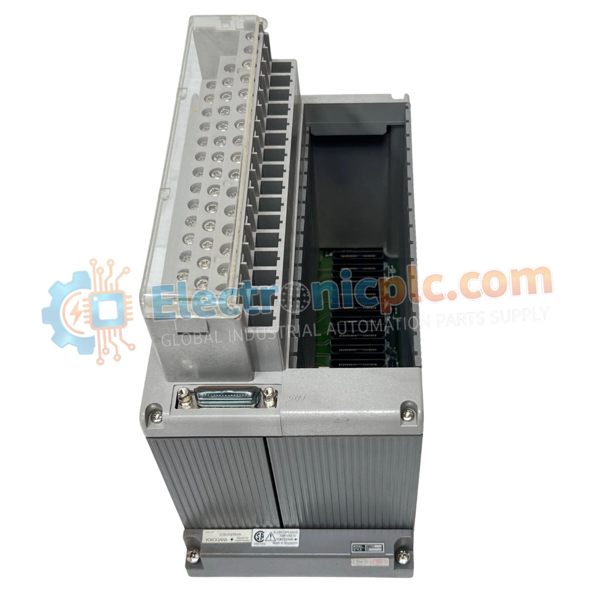
Configured for high-density signal integration in control networks, the Yokogawa AMN11 and AMN22 (AMN11/AMN22 Analog I/O Module Nests) provide direct physical/electrical execution of modular backplane routing for AAM and AMM series analog components within Yokogawa industrial control systems.
| Parameter | Specification |
|---|---|
| Model Series | AMN11 / AMN22 |
| Brand | Yokogawa |
| Origin | Japan |
| Weight | 1.5 kg |
| Dimensions | 12.6 cm x 2.2 cm x 12.4 cm |
| Operating Temp | 0 to 50 deg C |
| Component Type | Analog I/O Module Nest (Base Rack) |
| Backplane Interface | High-density integrated connectors |
The AMN11/AMN22 series serves as the foundational interface for analog data acquisition, providing a stable backplane bus for AAM and AMM series modules. The industrial-grade chassis incorporates EMC shielding to mitigate electromagnetic interference, ensuring that low-level voltage inputs and 4-20 mA HART loop protocol signals remain free of noise-induced degradation. By consolidating signal routing in a compact footprint, these nests optimize space within marshaling cabinets while maintaining the electrical isolation required for high-accuracy process control.
Q: Are the AMN11 and AMN22 nests compatible with all AAM/AMM series modules?
A: These nests are designed for compatibility with standard AAM and AMM analog I/O modules; however, ensure the specific module revision is supported by the nest backplane interface prior to installation.
Q: Do these nests require a separate chassis ground connection?
A: Yes, to maintain the effectiveness of the integrated EMC shielding, the metallic chassis must be bonded to the main cabinet ground bus using a low-impedance connection.


