سلة التسوق الخاصة بي
0 عنصرًا
قطع غيار أصلية للأتمتة | توصيل سريع عالمي | ضمان لمدة 12 شهرًا — [احصل على عرض سعر]

تم تكوين Yokogawa AMN51 (AMN51 Nest لبطاقات الاتصال) لدمج الإشارات عالية الكثافة في شبكات التحكم، ويوفر هذا الجهاز تنفيذًا ماديًا/كهربائيًا مباشرًا للتوجيه الخلفي المعياري لمكونات الاتصال داخل محطات التحكم الميدانية...
التوافر: الكمية المتبقية: 99
توصيل موثوق به في جميع أنحاء العالم
ضمان استرداد الأموال خلال 30 يومًا
هل تحتاج إلى مزيد من التفاصيل؟ اقرأ سياسة الشحن وسياسة الاسترداد الكاملة.
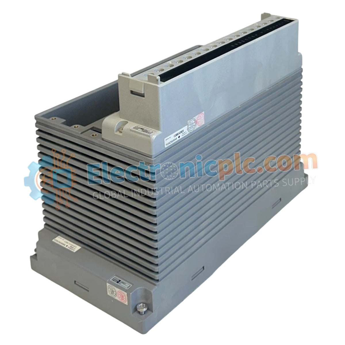
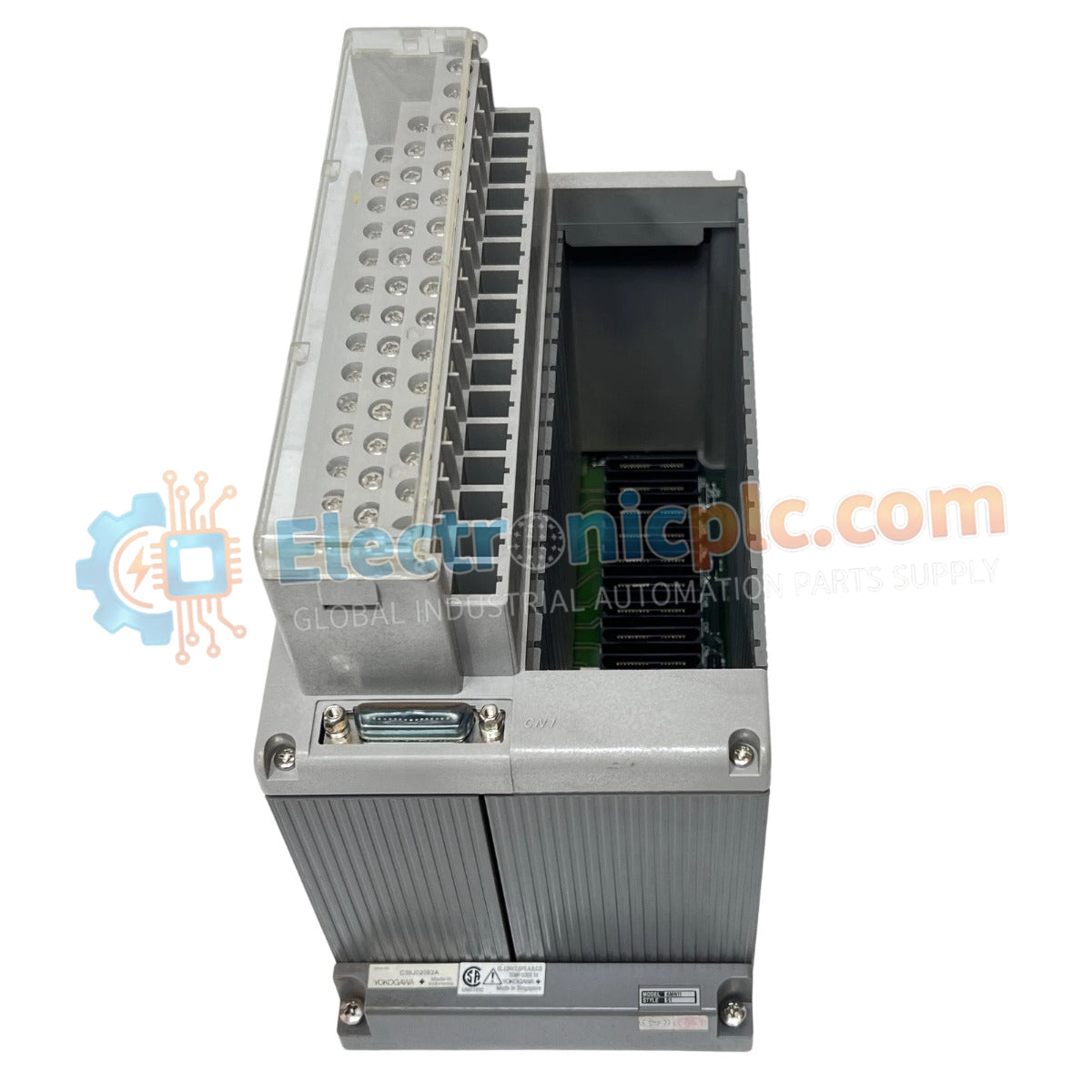
تم تكوين Yokogawa AMN51 (AMN51 Nest لبطاقات الاتصال) لدمج الإشارات عالية الكثافة في شبكات التحكم، ويوفر هذا الجهاز تنفيذًا ماديًا/كهربائيًا مباشرًا للتوجيه الخلفي المعياري لمكونات الاتصال داخل محطات التحكم الميدانية من Yokogawa.
| المعلمة | المواصفات |
|---|---|
| النموذج | AMN51 |
| العلامة التجارية | يوكوجاوا |
| الأصل | اليابان |
| الوزن | 2.5 كجم |
| الأبعاد | 137.5 ملم × 225 ملم × 254 ملم |
| درجة حرارة التشغيل | 0 إلى 50 درجة مئوية |
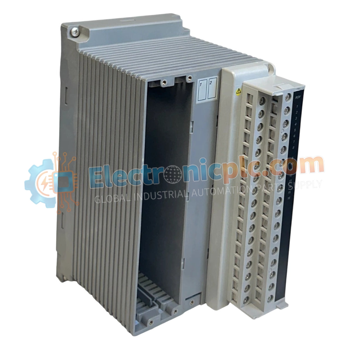
| مزود الطاقة | 5.0 فولت تيار مستمر |
| مصدر الطاقة | AND50، ANS50، AND20، ANS20، أو PFCS/PFCD |
| التركيب | وحدة واجهة العقدة، رف توسيع الإدخال/الإخراج، PFCS/PFCD |
يعمل مأخذ AMN51 كواجهة أساسية لبطاقات الاتصال في معماريات نظام التحكم الموزع (DCS) من Yokogawa. من خلال استخدام مصدر طاقة ثابت 5.0 فولت تيار مستمر مشتق من وحدات واجهة العقدة أو محطات التحكم الميدانية (PFCS/PFCD)، يضمن المأخذ توصيل طاقة ثابتًا للحفاظ على إنتاجية بطاقة الاتصال وسلامة الإشارة. يسهل التصميم الميكانيكي الاندماج في تكوينات محطات التحكم الميدانية المختلفة، مما يدعم بروتوكولات تبادل البيانات عالية السرعة المطلوبة للمراقبة والتحكم في العمليات في الوقت الفعلي.
س: هل مأخذ AMN51 متوافق مع مصادر طاقة أخرى غير وحدات سلسلة AND/ANS المحددة؟
ج: تم تصميم المأخذ بدقة لمدخل 5.0 فولت تيار مستمر من وحدات واجهة العقدة المذكورة أو محطات PFCS/PFCD؛ قد يؤدي استخدام مصادر طاقة غير مصرح بها إلى فشل الأجهزة أو عدم استقرار الاتصال.
س: هل يمكن تركيب مأخذ AMN51 في رف توسيع الإدخال/الإخراج بدون وحدة واجهة العقدة؟
ج: تم تصميم المأخذ للاستخدام داخل رفوف توسيع الإدخال/الإخراج أو وحدات واجهة العقدة، شريطة أن يوفر الرف اتصال ناقل 5.0 فولت تيار مستمر اللازم والعزل الكهربائي المطلوب بواسطة بطاقات الاتصال.


