
سلة التسوق الخاصة بي
0 عنصرًا
قطع غيار أصلية للأتمتة | توصيل سريع عالمي | ضمان لمدة 12 شهرًا — [احصل على عرض سعر]

تعمل وحدة YOKOGAWA F3AD04-5V، والمُدرجة أيضًا ضمن الكتالوج باسم وحدة الإدخال التناظري F3AD04، كمكون مادي مخصص لاكتساب الإشارة التناظرية عالية الكثافة ضمن منصات وحدات التحكم المنطقية القابلة للبرمجة من السلسلة F3.
التوافر: في الأوراق المالية
توصيل موثوق به في جميع أنحاء العالم
ضمان استرداد الأموال خلال 30 يومًا
هل تحتاج إلى مزيد من التفاصيل؟ اقرأ سياسة الشحن وسياسة الاسترداد الكاملة.


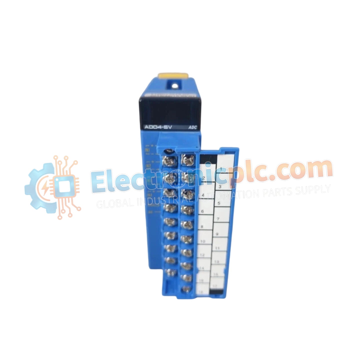
تعمل وحدة YOKOGAWA F3AD04-5V، والمُدرجة أيضًا ضمن الكتالوج باسم وحدة الإدخال التناظري F3AD04، كمكون مادي مخصص لاكتساب الإشارة التناظرية عالية الكثافة ضمن منصات وحدات التحكم المنطقية القابلة للبرمجة من السلسلة F3.
F3: بادئة السلسلة تشير إلى التوافق مع أنظمة الرفوف الخلفية القياسية F3.
AD: تعيين وظيفة الإدخال التناظري إلى الرقمي.
04: تكوين أربع قنوات إدخال تفاضلية.
5V: تشغيل مصدر طاقة اللوحة الخلفية 5 VDC.
| المعلمة | المواصفات |
| النموذج | F3AD04-5V |
| العلامة التجارية | YOKOGAWA |
| المنشأ | سنغافورة |
| الوزن | 0.2 كجم |
| الأبعاد | 28.9 ملم (عرض) × 100 ملم (ارتفاع) × 106.1 ملم (عمق) |
| درجة حرارة التشغيل | 0 درجة مئوية إلى 55 درجة مئوية |
| استهلاك الطاقة | 5 VDC اسمي |
| قنوات الإدخال | 4 تفاضلية |
تم تصميم F3AD04-5V للاندماج في شبكات التحكم الحتمية، مما يضمن توقيتًا دقيقًا لدورات التحويل التناظري إلى الرقمي. تدعم بنية الوحدة الاتصال عالي السرعة عبر ناقل اللوحة الخلفية، مما يمكّن معالج PLC من مزامنة اكتساب البيانات مع تنفيذ المنطق في الوقت الفعلي. يستخدم التصميم مدخلات تفاضلية عالية المعاوقة لتقليل تأثيرات التحميل على أدوات المجال، مع الحفاظ على دقة الإشارة في تطبيقات قياس كثافة الإدخال/الإخراج المعقدة.
س: هل تدعم F3AD04-5V التبديل السريع على اللوحة الخلفية F3؟
ج: لا، لا تدعم الوحدة التبديل السريع. يجب إيقاف تشغيل طاقة الرف قبل إدخال الوحدة أو إزالتها لمنع حدوث قوس كهربائي وأخطاء اتصال ناقل اللوحة الخلفية.
س: هل القنوات الأربع للإدخال التفاضلي معزولة كهربائيًا عن بعضها البعض؟
ج: تتميز F3AD04-5V بمدخلات تفاضلية؛ ومع ذلك، استشر الدليل الفني للحصول على تقييمات العزل الجلفاني المحددة. في التطبيقات ذات الفولتية المشتركة العالية، يلزم وجود عوازل إشارة خارجية لحماية دائرة إدخال الوحدة.
تأكد من أن رف القاعدة F3 مؤرض بشكل صحيح إلى قضيب التأريض الواقي للخزانة لضمان التوافق الكهرومغناطيسي وسلامة الأفراد.
قم بمحاذاة الوحدة مع أدلة الفتحة المقصودة على رف اللوحة الخلفية. اضغط باستمرار حتى يتم تثبيت الوحدة بالكامل وتكون ذراع القفل معشقة.
بالنسبة للإشارات التفاضلية، قم بتوصيل كلا طرفي الإشارة الموجب والسالب بالكتلة الطرفية المخصصة. تأكد من استخدام كابلات مجدولة ومحمية لتقليل التداخل الكهرومغناطيسي.
قم بتأريض درع الكابل عند نقطة إنهاء واحدة، ويفضل أن يكون ذلك عند قضيب التأريض الخاص بأجهزة الخزانة، لمنع حلقات التأريض التي قد تتسبب في تشويش الإشارة.
بعد التثبيت، قم بإجراء فحص لتكوين البرنامج للتأكد من أن وحدة المعالجة المركزية (CPU) تحدد قنوات الإدخال بدقة وأن القيم الرقمية المحولة ترتبط بمستويات الإشارة الميدانية.


