سلة التسوق الخاصة بي
0 عنصرًا
قطع غيار أصلية للأتمتة | توصيل سريع عالمي | ضمان لمدة 12 شهرًا — [احصل على عرض سعر]

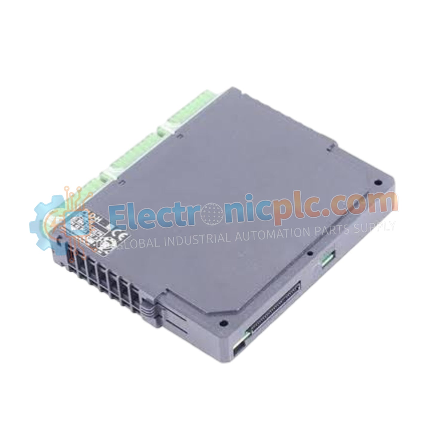
Configured for precision signal acquisition within MICREX-SX SPH control architectures, the Yokogawa NP1AX04-MR (NP1AX04-MR Analog Input Module) provides direct physical and electrical execution of 4-channel analog signal processing.
التوافر: في الأوراق المالية
توصيل موثوق به في جميع أنحاء العالم
ضمان استرداد الأموال خلال 30 يومًا
هل تحتاج إلى مزيد من التفاصيل؟ اقرأ سياسة الشحن وسياسة الاسترداد الكاملة.

Configured for precision signal acquisition within MICREX-SX SPH control architectures, the Yokogawa NP1AX04-MR (NP1AX04-MR Analog Input Module) provides direct physical and electrical execution of 4-channel analog signal processing.
| Parameter | Specification |
|---|---|
| Model | NP1AX04-MR |
| Brand | Yokogawa |
| Origin | Japan |
| Weight | 0.2 kg |
| Dimensions | 3.8 cm x 10.2 cm x 10.2 cm |
| Operating Temp | Standard industrial range |
| Power Consumption | Backplane dependent |
| Input Channels | 4 channels |
| Resolution | 10-bit |
| Signal Range | Multi-range (voltage/current configurable) |
The NP1AX04-MR architecture is optimized for high-performance data acquisition within the MICREX-SX SPH series. The module manages deterministic signal capture, ensuring that backplane bus communication velocity remains consistent during multi-channel polling. The hardware utilizes configurable input stages that allow the user to define voltage or current ranges to match specific field device outputs. By implementing internal signal conditioning and filtering, the module maintains a high level of accuracy across the 10-bit resolution range, ensuring that process variables are relayed to the CPU without significant quantization error or noise ingress from the field loop.
Q: Does the NP1AX04-MR support hot-swapping during active PLC operation?
A: No. To prevent potential backplane bus communication faults or short-circuits at the connector pins, ensure the PLC rack power is completely de-energized before performing module insertion or removal.
Q: How is the multi-range configuration applied to individual channels?
A: The input ranges are typically selected via software configuration within the MICREX-SX programming environment or through hardware dip-switch settings on the module side, depending on the specific firmware revision. Refer to the system hardware manual to confirm the configuration method for your specific installation.

