سلة التسوق الخاصة بي
0 عنصرًا
قطع غيار أصلية للأتمتة | توصيل سريع عالمي | ضمان لمدة 12 شهرًا — [احصل على عرض سعر]

The YOKOGAWA SAI143-S63, also cataloged as the SAI143 Analog Input Module, operates as a dedicated hardware component for 16-channel analog current signal acquisition within Yokogawa CENTUM VP and ProSafe-RS control system...
التوافر: في الأوراق المالية
توصيل موثوق به في جميع أنحاء العالم
ضمان استرداد الأموال خلال 30 يومًا
هل تحتاج إلى مزيد من التفاصيل؟ اقرأ سياسة الشحن وسياسة الاسترداد الكاملة.
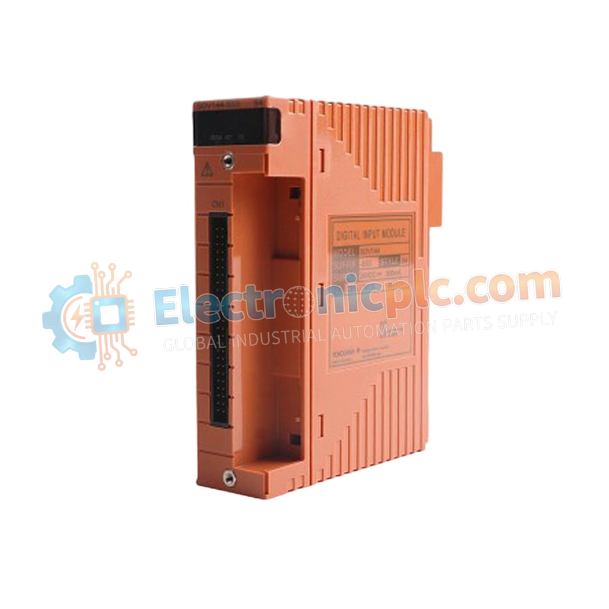
The YOKOGAWA SAI143-S63, also cataloged as the SAI143 Analog Input Module, operates as a dedicated hardware component for 16-channel analog current signal acquisition within Yokogawa CENTUM VP and ProSafe-RS control system platforms.
The SAI143-S63 utilizes a standardized suffix configuration for hardware version control. The -S63 designator identifies the module as a high-density input unit compliant with specific safety and environment-hardened standards required for operation in integrated DCS/SIS control environments.
| Parameter | Specification |
|---|---|
| Model | SAI143-S63 |
| Brand | YOKOGAWA |
| Origin | Japan |
| Weight | 0.3 kg |
| Dimensions | 3.2 cm x 10.7 cm x 13 cm |
| Operating Temp | -20 deg C to 70 deg C |
| Power Consumption | 5 VDC nominal |
| Input Channels | 16 (isolated) |
| Input Signal Range | 4-20 mA DC |
| Allowable Input Current | 24 mA max |
| Withstanding Voltage | 1500 V AC (1 minute) |
The SAI143-S63 is engineered with robust galvanic isolation between the field input stage and the internal system bus. This isolation is required to prevent ground potential interference and suppress electrical transients originating from field-side instrumentation. The module facilitates accurate 4-20 mA current monitoring while maintaining compliance with rigorous industrial control standards. By providing independent isolation for each of the 16 channels, the module ensures that electrical faults in one loop do not propagate to the control system backplane.
Q: Does the SAI143-S63 require external loop power?
A: Yes. The module is designed to receive 4-20 mA input signals. The field instruments must be powered via an external 24 VDC source or through an appropriate terminal board that supplies loop power to the field devices.
Q: Is this module compatible with HART loop protocol devices?
A: The SAI143-S63 is designed to pass 4-20 mA signals. When used in conjunction with specific Yokogawa terminal boards or HART-enabled interface modules, it can facilitate HART signal communication between field devices and the DCS.
