سلة التسوق الخاصة بي
0 عنصرًا
قطع غيار أصلية للأتمتة | توصيل سريع عالمي | ضمان لمدة 12 شهرًا — [احصل على عرض سعر]

Configured for safety-critical signal transmission in ProSafe-RS safety instrumented systems, the Yokogawa SAI533-H33 (SAI533 Analog Output Module) provides direct physical/electrical execution of 8-channel isolated analog current control.
التوافر: في الأوراق المالية
توصيل موثوق به في جميع أنحاء العالم
ضمان استرداد الأموال خلال 30 يومًا
هل تحتاج إلى مزيد من التفاصيل؟ اقرأ سياسة الشحن وسياسة الاسترداد الكاملة.

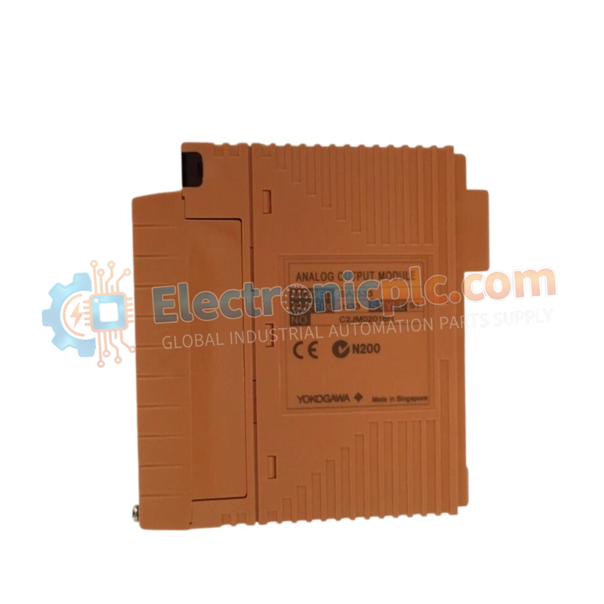
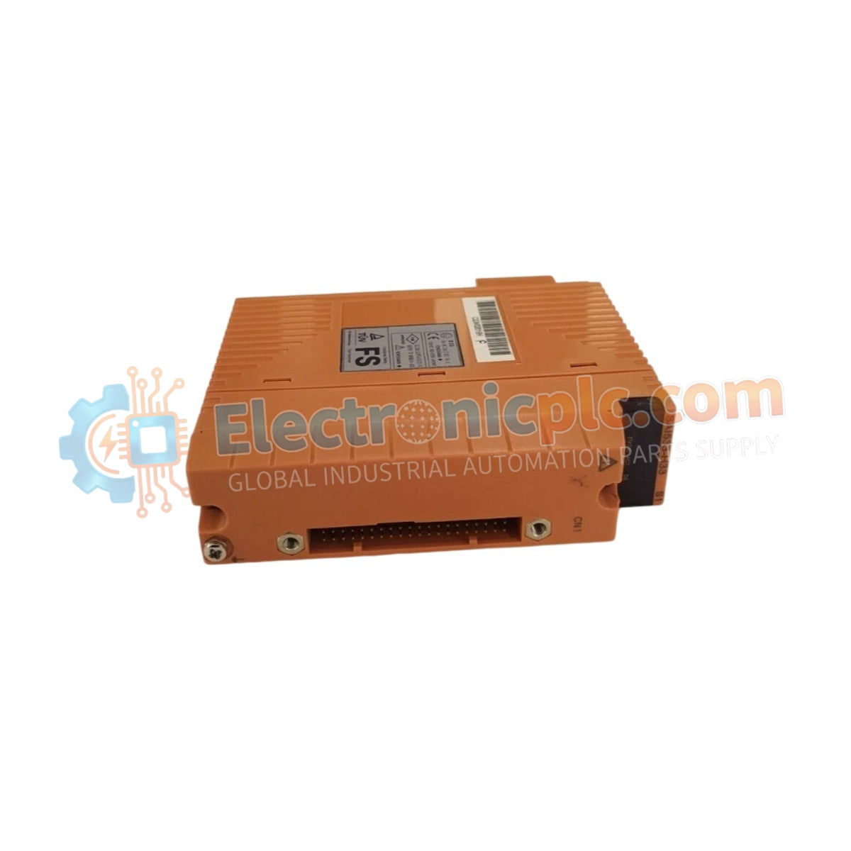
Configured for safety-critical signal transmission in ProSafe-RS safety instrumented systems, the Yokogawa SAI533-H33 (SAI533 Analog Output Module) provides direct physical/electrical execution of 8-channel isolated analog current control.
| Parameter | Specification |
|---|---|
| Model | SAI533-H33 |
| Brand | Yokogawa |
| Origin | Japan |
| Weight | 0.34 kg |
| Dimensions | 130 mm x 124 mm x 32.8 mm |
| Operating Temp | Standard industrial range |
| Power Consumption | System-dependent load |
| Output Channels | 8 isolated channels |
| Output Range | 1.25 mA to 23 mA (4-20 mA rated) |
| Accuracy | +/- 48 uA |
| Load Resistance | 230 Ohm to 600 Ohm |
| Update Cycle | 40 ms |
The SAI533-H33 functions as a dedicated hardware component for driving field devices such as actuators and control valves within SIS platforms. The architecture supports triple modular redundancy (TMR) to facilitate high-availability logic execution and fail-safe state transitions in the event of an internal fault. Galvanic isolation between channels and the system bus prevents ground loop interference, ensuring the integrity of the 4-20 mA loop protocol under extreme process conditions. The module is engineered for deployment in hazardous areas, necessitating strictly controlled installation practices to maintain its safety-certified electrical characteristics.
Q: Does the SAI533-H33 support redundancy in control loop configurations?
A: Yes. The module is designed to operate within dual-redundant or TMR configurations, ensuring that a single module failure does not compromise the overall safety loop.
Q: Is it permissible to exceed the 600 Ohm load resistance limit during installation?
A: No. Operating with a load resistance outside the 230 Ohm to 600 Ohm range can lead to voltage saturation at the output driver, resulting in signal clipping and loss of the rated 4-20 mA precision.


