سلة التسوق الخاصة بي
0 عنصرًا
قطع غيار أصلية للأتمتة | توصيل سريع عالمي | ضمان لمدة 12 شهرًا — [احصل على عرض سعر]

Configured for high-precision frequency and pulse signal acquisition within DCS architectures, the Yokogawa AP135-S00 (AP135-S00 Pulse Input Module) provides direct physical and electrical processing of 8-channel pulse-based process data within...
التوافر: في الأوراق المالية
توصيل موثوق به في جميع أنحاء العالم
ضمان استرداد الأموال خلال 30 يومًا
هل تحتاج إلى مزيد من التفاصيل؟ اقرأ سياسة الشحن وسياسة الاسترداد الكاملة.

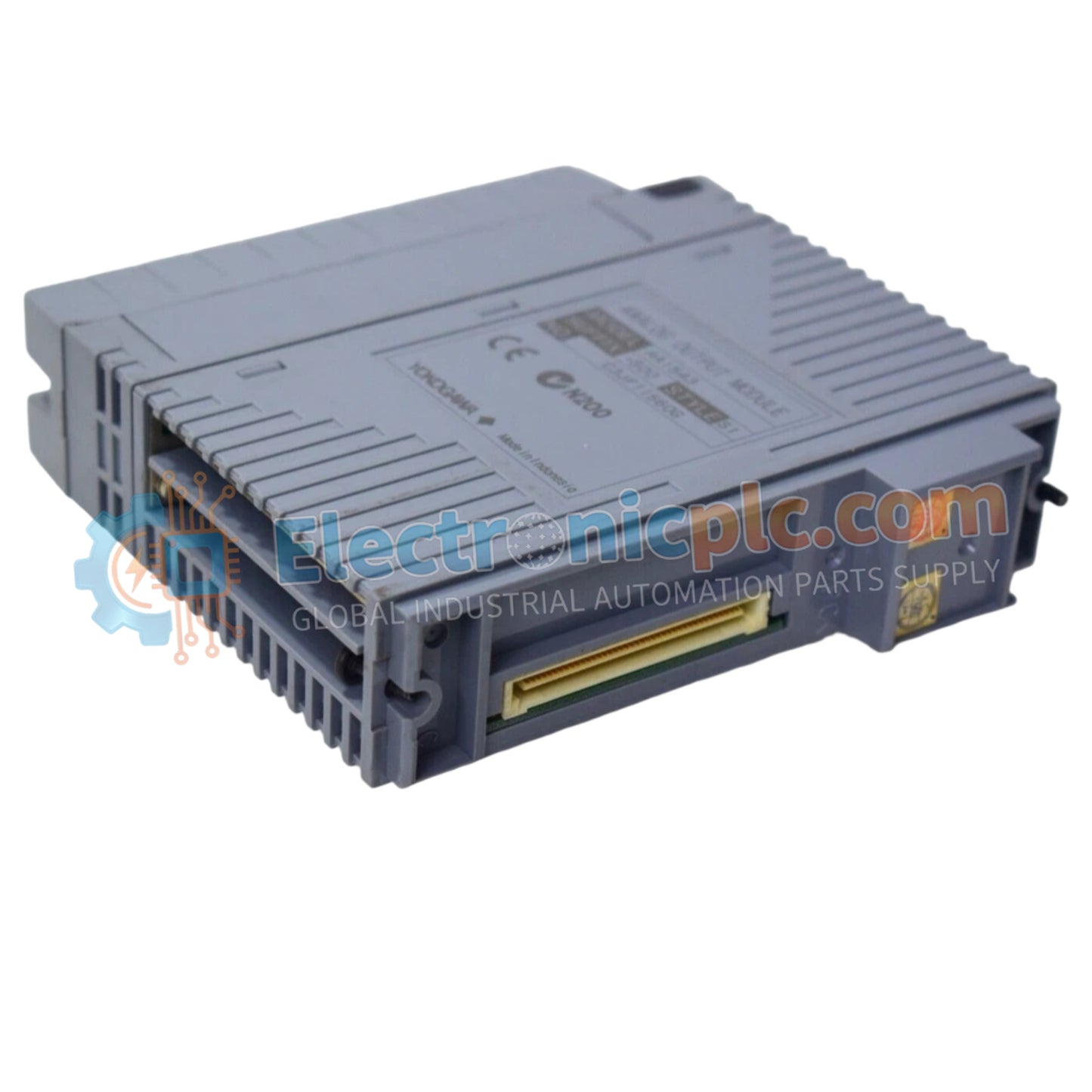
Configured for high-precision frequency and pulse signal acquisition within DCS architectures, the Yokogawa AP135-S00 (AP135-S00 Pulse Input Module) provides direct physical and electrical processing of 8-channel pulse-based process data within CENTUM VP and CENTUM CS platforms.
| Parameter | Specification |
|---|---|
| Model | AP135-S00 |
| Brand | Yokogawa |
| Origin | Japan |
| Weight | 0.5 kg |
| Dimensions | 230 mm x 110 mm x 30 mm |
| Operating Temp | -20 deg C to +70 deg C |
| Power Consumption | 10 W |
| Input Channels | 8 channels |
| Signal Types | Contact, voltage, current pulse |
| Input Frequency | 0 to 800 Hz |
| Accuracy | +/- 0.1% of full scale |
| Isolation | 500 V AC |
The AP135-S00 is engineered to provide robust signal isolation between field-side pulse transmitters and the DCS backplane. The module supports a diverse range of pulse input types, including contact state, voltage, and current pulses, making it highly effective for metering and flow measurement applications where precision is paramount. The internal architecture features channel-to-channel isolation, which is critical in preventing ground loop interference and minimizing common-mode noise across the 8-channel array. With an input frequency range of up to 800 Hz, the unit ensures deterministic pulse counting for rapid process transients.
Q: Can the AP135-S00 be used for safety-critical speed monitoring?
A: While the module provides accurate pulse counting, ensure that the specific loop requirements are verified against the system's safety documentation; always use dedicated safety-rated modules for SIL-certified safety instrumented systems.
Q: What is the significance of the 500 V AC isolation voltage rating?
A: The isolation rating ensures that high-voltage potential differences between field devices and the DCS cabinet do not damage the module or corrupt data on the internal backplane, providing a reliable barrier against electrical faults.

