سلة التسوق الخاصة بي
0 عنصرًا
قطع غيار أصلية للأتمتة | توصيل سريع عالمي | ضمان لمدة 12 شهرًا — [احصل على عرض سعر]

Configured for high-speed signal protection within industrial control networks, the Yokogawa TAS21 (TAS21 Coaxial Lightning Arrester) provides direct physical surge suppression for V net and ER bus platforms.
التوافر: في الأوراق المالية
توصيل موثوق به في جميع أنحاء العالم
ضمان استرداد الأموال خلال 30 يومًا
هل تحتاج إلى مزيد من التفاصيل؟ اقرأ سياسة الشحن وسياسة الاسترداد الكاملة.

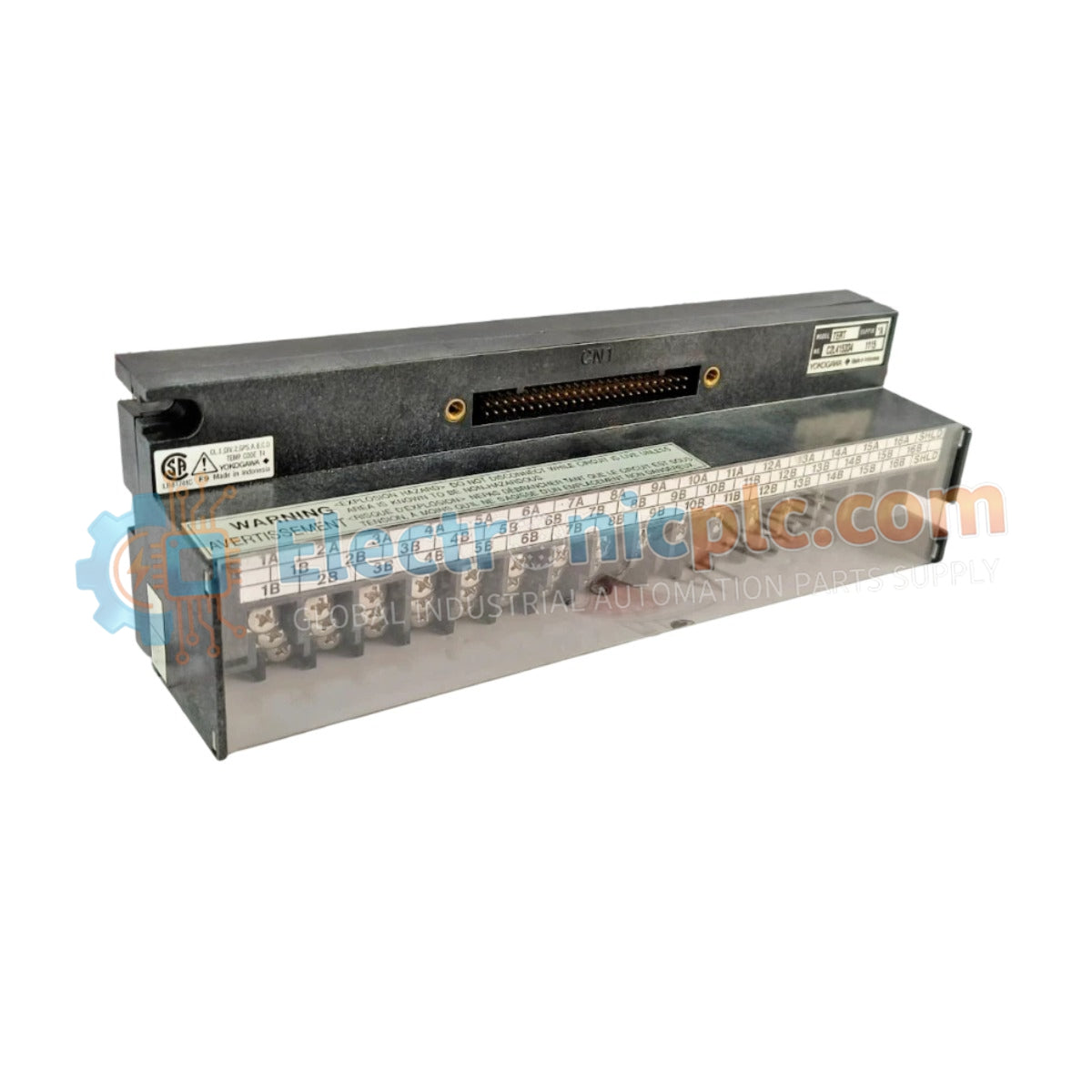
Configured for high-speed signal protection within industrial control networks, the Yokogawa TAS21 (TAS21 Coaxial Lightning Arrester) provides direct physical surge suppression for V net and ER bus platforms.
| Parameter | Specification |
|---|---|
| Model | TAS21 |
| Brand | Yokogawa |
| Origin | japan |
| Weight | 1.1kg |
| Dimensions | Industrial metallic enclosure |
| Operating Temp | Standard industrial range |
| Power Consumption | Passive component |
| Impedance | 50 Ohm |
| Frequency Range | Up to 2.5 GHz |
| Discharge Capacity | 10 kA per pulse |
| Insertion Loss | < 0.2 dB |
The TAS21 is engineered to maintain low-latency data flow within Yokogawa CENTUM VP and ProSafe-RS architectures while providing critical transient voltage suppression. The arrester utilizes intrinsic safety (Ex i) barrier-compatible construction principles to ensure that high-energy surges, such as those induced by lightning strikes, are shunted to the system earth bus before reaching sensitive communication modules. The metallic enclosure provides robust electromagnetic interference (EMI) shielding, maintaining protocol integrity and preventing communication latencies that could otherwise destabilize deterministic V net or 10BASE-5 network segments.
Q: Does the TAS21 require periodic replacement after a surge event?
A: While the device is rated for high discharge capacity, it should be tested for continuity and insertion loss after any significant surge event. If the device exhibits elevated resistance or increased attenuation, it must be replaced to ensure ongoing hardware protection.
Q: Can the arrester be installed in series with standard coaxial network cables?
A: Yes. The TAS21 is designed for insertion into the network path using standard N-type connectors. Ensure that the device is installed as close to the entry point of the communication line into the control cabinet as possible to maximize the protection of internal DCS components.

