
سلة التسوق الخاصة بي
0 عنصرًا
قطع غيار أصلية للأتمتة | توصيل سريع عالمي | ضمان لمدة 12 شهرًا — [احصل على عرض سعر]

تعمل وحدة YOKOGAWA NFCP050، المصنفة أيضًا كوحدة المعالجة المركزية NFCP050، كمكون أجهزة مخصص للتحكم في العمليات المحلية وتنفيذ المنطق ضمن بنى نظام FCN-RTU. توفر هذه الوحدة معالجة مركزية عالية السرعة وتكييفًا متكاملاً...
التوافر: في الأوراق المالية
توصيل موثوق به في جميع أنحاء العالم
ضمان استرداد الأموال خلال 30 يومًا
هل تحتاج إلى مزيد من التفاصيل؟ اقرأ سياسة الشحن وسياسة الاسترداد الكاملة.


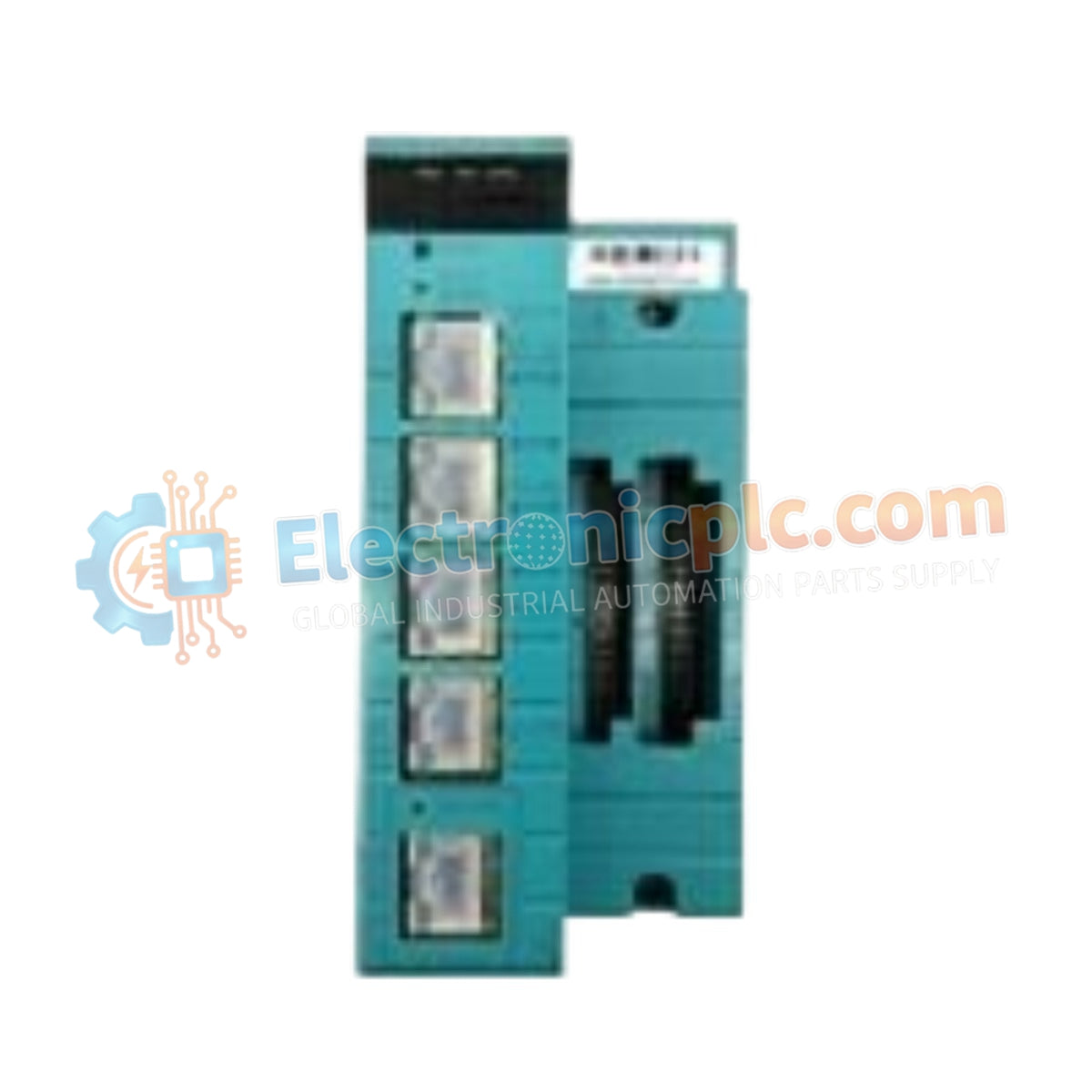
تعمل وحدة YOKOGAWA NFCP050، المصنفة أيضًا كوحدة المعالجة المركزية NFCP050، كمكون أجهزة مخصص للتحكم في العمليات المحلية وتنفيذ المنطق ضمن بنى نظام FCN-RTU. توفر هذه الوحدة معالجة مركزية عالية السرعة وتكييفًا متكاملاً للإشارة لمتطلبات الإدخال/الإخراج الميدانية المتنوعة.
| المعلمة | المواصفات |
| النموذج | NFCP050 |
| العلامة التجارية | YOKOGAWA |
| المنشأ | اليابان |
| الوزن | 0.57 كجم |
| الأبعاد | 14.25 سم × 6.58 سم × 13 سم |
| درجة حرارة التشغيل | -20 درجة مئوية إلى 70 درجة مئوية |
| استهلاك الطاقة | 12 واط نموذجي |
| وحدة المعالجة المركزية | SH-4A (SH7730) 256 ميجاهرتز |
| الذاكرة | 128 ميجابايت فلاش مدمج |
| سعة الإدخال/الإخراج | 16 DI، 8 DO، 13 AI، 2 AO، 2 PI |
تتكامل وحدة المعالجة المركزية NFCP050 مباشرة مع حلقات التحكم في العمليات، وتدعم بروتوكول حلقة HART 4-20 مللي أمبير للقياس الموحد. يشتمل التصميم على عزل من قناة إلى قناة للمدخلات التناظرية الحرجة، مما يضمن معالجة إشارة دقيقة في خزانات القياس متعددة الحلقات. تسهل المنصة اتصال FOUNDATION Fieldbus، مما يتيح التكامل السلس في بيئات DCS القائمة مع الحفاظ على تبادل البيانات المحدد لتطبيقات التحكم في الوقت الفعلي.
س: هل يدعم NFCP050 التبديل الساخن في ظل ظروف التشغيل العادية؟
ج: لم يتم تصميم وحدة NFCP050 للتبديل الساخن. يجب فصل طاقة النظام قبل إزالة الوحدة أو تركيبها لمنع تلف دبابيس اللوحة الخلفية والتلف المحتمل للذاكرة غير المتطايرة.
س: هل منافذ الاتصال RS-232 و RS-422/RS-485 معزولة كهربائيًا؟
ج: لا، واجهات الاتصال في NFCP050 غير معزولة. يجب على المستخدمين التأكد من التأريض الصحيح للإشارة وتنفيذ حواجز عزل جلفانية خارجية عند الاتصال بالأجهزة الميدانية الموجودة في بيئات عالية الضوضاء أو عبر مناطق جهد مختلفة.
قم بتركيب الوحدة داخل الوحدة الأساسية FCN-RTU، مع التأكد من محاذاة موصلات اللوحة الخلفية بشكل صحيح وأن ألسنة التثبيت مثبتة بالكامل لمنع فقدان الإشارة المتقطع.
تأكد من أن جهد الإدخال يتطابق مع النطاق المقدر لنظام FCN-RTU؛ تحقق من جميع قطبي الأسلاك لحلقة 4-20 مللي أمبير وإشارات الإدخال الرقمية قبل التشغيل.
استخدم الكابلات المجدولة المزدوجة المجدولة لجميع منافذ الاتصال التسلسلي. يجب إنهاء الدرع عند نقطة أرضية مشتركة واحدة لتقليل تيارات الحلقة الأرضية وحساسية EMI.
حافظ على مسافة لا تقل عن 50 مم حول فتحات تهوية الوحدة لمنع تراكم الحرارة، مما يضمن بقاء التشغيل ضمن حدود درجة الحرارة المحيطة المحددة.
قم بإجراء تسلسل تمهيد بارد بعد التشغيل الأولي للتحقق من تهيئة البرامج الثابتة واجتياز التشخيص الأساسي لوحدة المعالجة المركزية ودوائر الإدخال/الإخراج الداخلية.


