انتقل إلى معلومات المنتج
1 ل 3

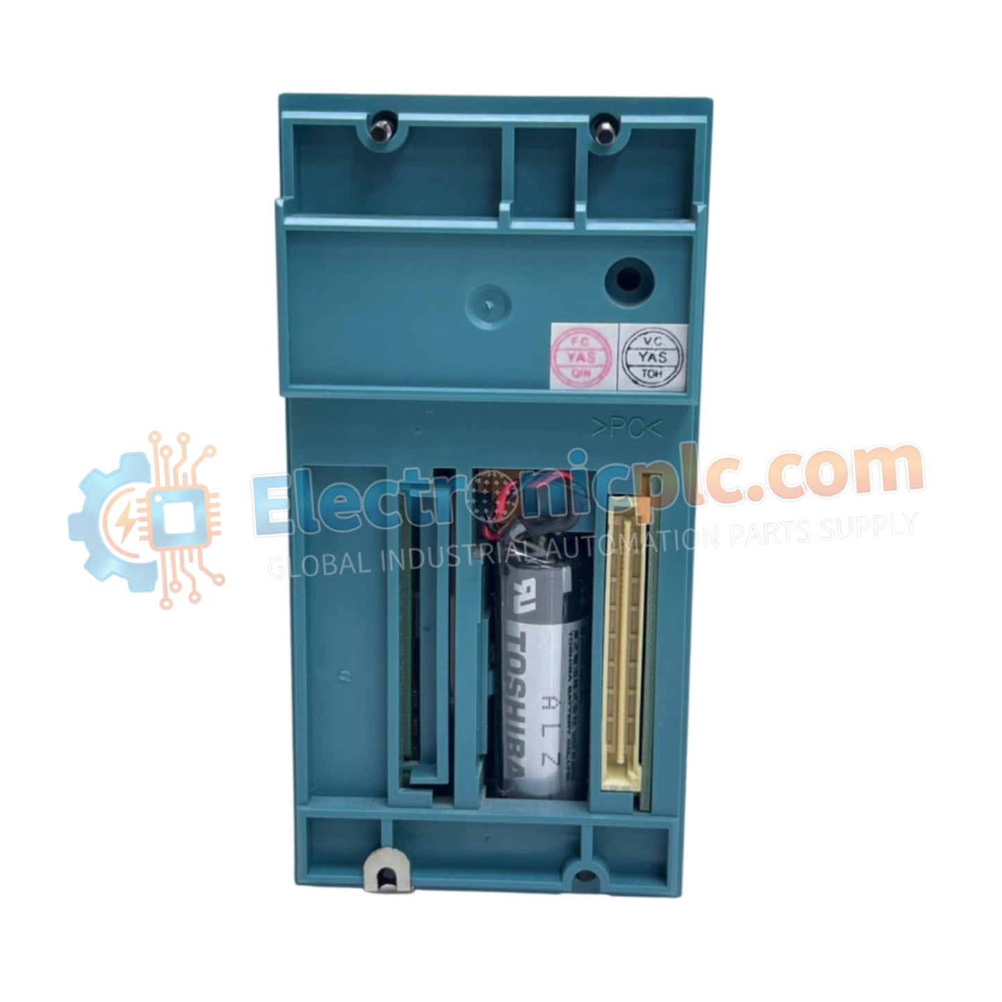
CPU Module YOKOGAWA NFCP100-S05

CPU Module YOKOGAWA NFCP100-S05

The YOKOGAWA NFCP100-S05, also cataloged as the NFCP100 CPU Module, operates as a dedicated hardware component for deterministic logic execution and process control within STARDOM network platforms.

Hardware Specifications

22 يشاهد الناس هذا الآن

التوافرفي الأوراق المالية

رمز المنتج: NFCP100-S05
بائع: Yokogawa
فئة: CPU Module
Related Series:

الشحن والإرجاع

توصيل موثوق به في جميع أنحاء العالم

  • شركات الشحن: يتم الشحن عبر DHL أو FedEx أو UPS أو USPS .
  • الشحن: تتم معالجة الطلبات خلال يوم عمل واحد إلى يومين، ويتم شحنها خلال 3 إلى 5 أيام عمل .
  • التتبع: يتم توفير تفاصيل التتبع الكاملة عبر البريد الإلكتروني عند الشحن.

ضمان استرداد الأموال خلال 30 يومًا

  • الضمان: فترة إرجاع لمدة 30 يومًا للمنتجات المتوفرة في المخزون والمغلفة من المصنع.
  • الشروط: يجب أن تكون المنتجات غير مفتوحة وغير مستخدمة وفي عبوتها الأصلية.
  • الأصالة: نضمن أن تكون الأجهزة أصلية 100% .

هل تحتاج إلى مزيد من التفاصيل؟ اقرأ سياسة الشحن وسياسة الاسترداد الكاملة.

الأصالة والضمان

  • ضمان أصلي: نحن نوفر فقط قطع غيار أصلية 100%، جديدة تمامًا، ومغلقة من المصنع .
  • تغطية كاملة: كل مكون مدعوم بضمان شامل لمدة 12 شهرًا من تاريخ الشراء.
  • إمكانية التتبع: جميع المنتجات تأتي مع وثائق المصنع الأصلية والملحقات اللازمة للامتثال الكامل للمعايير الصناعية.

الدعم الفني والتوريد

  • مساعدة الخبراء: يقدم فريقنا الفني استشارات مجانية لمساعدتك في التحقق من التوافق مع أنظمة DCS و PLC.
  • مصادر القطع النادرة: متخصصون في المكونات القديمة والتي يصعب العثور عليها من Allen-Bradley و Siemens و ABB و HIMA وغيرها.
  • للاستفسارات المتعلقة بالكميات الكبيرة: تواصلوا معنا على pambo@5gplc.com للحصول على أسعار الكميات الكبيرة أو عروض أسعار المشاريع المخصصة.
عرض تفاصيل المنتج الكاملة

The YOKOGAWA NFCP100-S05, also cataloged as the NFCP100 CPU Module, operates as a dedicated hardware component for deterministic logic execution and process control within STARDOM network platforms.

Hardware Specifications

Parameter Specification
Model NFCP100-S05
Brand YOKOGAWA
Origin Japan
Weight 1.5 kg
Dimensions 230 mm x 130 mm x 60 mm
Operating Temp -20 deg C to 60 deg C
Power Consumption 30 W
CPU 32-bit RISC processor
Memory 256 MB DRAM with ECC
Interfaces Ethernet, H1 FOUNDATION Fieldbus, RS-232C, RS-485

FOUNDATION Fieldbus Connectivity and Network Integrity

The NFCP100-S05 provides integrated H1 FOUNDATION Fieldbus connectivity, facilitating direct communication with smart field instrumentation. This interface is engineered for high-availability network integration, supporting real-time data exchange and parameter diagnostics. The module utilizes ECC-protected DRAM to ensure computational integrity during complex control algorithm processing. For deterministic network behavior, the CPU architecture manages multi-protocol stacks—including Ethernet and serial interfaces—with specific latencies optimized for industrial loop control.

Frequently Asked Questions

Q: Does the NFCP100-S05 support firmware updates without replacing the hardware?

A: Yes, firmware updates are supported via the service interface. Ensure that a redundant power supply is active during the update process to prevent memory corruption or partial flash programming.

Q: What are the requirements for the RS-485 communication bus termination?

A: When utilizing the RS-485 interface for long-distance serial communication, a 120 Ohm terminating resistor must be applied at both ends of the physical bus to prevent signal reflections and data transmission errors.

Field Installation Guidelines

  1. Verify the rack power supply is set to 24 VDC and within nominal limits before inserting the CPU module into the STARDOM base unit.
  2. Ensure the module is fully aligned with the backplane connectors to prevent pin misalignment during the engagement of the locking mechanism.
  3. Utilize shielded, twisted-pair cabling for RS-485 and H1 FOUNDATION Fieldbus connections, ensuring that the cable shield is grounded at the designated common ground point to minimize EMI.
  4. Confirm that the status LEDs reflect a normal operating condition (no fault indicators) after the boot cycle is complete.
  5. Adhere to the vibration resistance limit of 0.5 mm peak-to-peak by securing the chassis to a rigid mounting surface, ensuring the ambient temperature remains within the -20 deg C to 60 deg C operational range.