سلة التسوق الخاصة بي
0 عنصرًا
قطع غيار أصلية للأتمتة | توصيل سريع عالمي | ضمان لمدة 12 شهرًا — [احصل على عرض سعر]

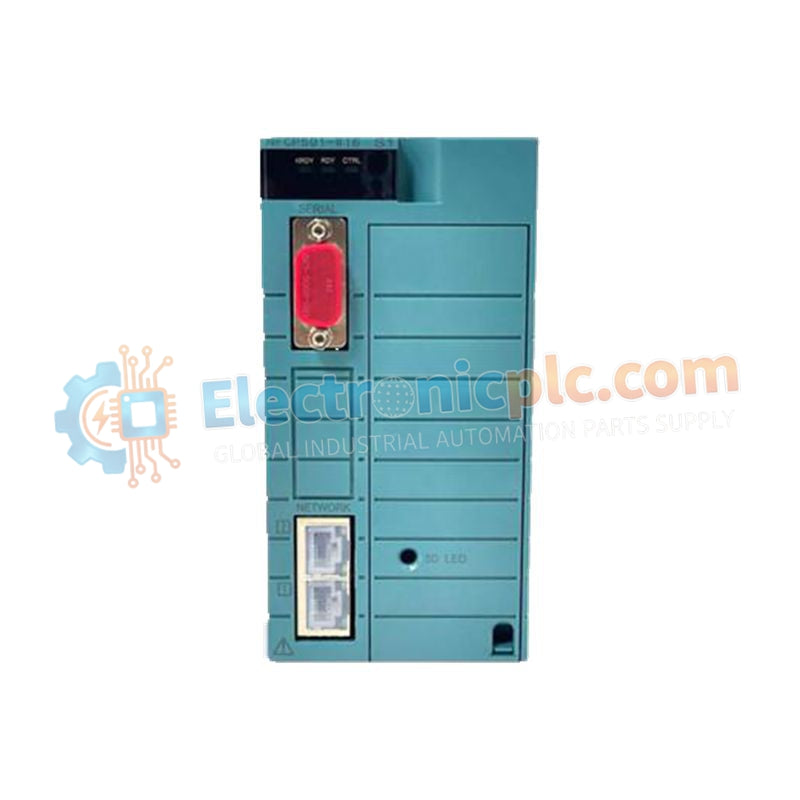
Configured for high-speed logic execution in STARDOM control networks, the Yokogawa NFCP501-W05/S01 (NFCP501-W05/S01 CPU Module) provides direct physical execution of IEC 61131-3 compliant control algorithms.
التوافر: الكمية المتبقية: 99
توصيل موثوق به في جميع أنحاء العالم
ضمان استرداد الأموال خلال 30 يومًا
هل تحتاج إلى مزيد من التفاصيل؟ اقرأ سياسة الشحن وسياسة الاسترداد الكاملة.

Configured for high-speed logic execution in STARDOM control networks, the Yokogawa NFCP501-W05/S01 (NFCP501-W05/S01 CPU Module) provides direct physical execution of IEC 61131-3 compliant control algorithms.
| Parameter | Specification |
|---|---|
| Model | NFCP501-W05/S01 |
| Brand | Yokogawa |
| Origin | Japan |
| Weight | 0.3 kg |
| Dimensions | 2.2 cm x 12.4 cm x 12.6 cm |
| Operating Temp | -25 deg C to +60 deg C |
| Power Consumption | Not specified (Standard backplane powered) |
| SDRAM | 128 MB |
| Flash Memory | 128 MB |
| Communication | 2 x Ethernet ports |
The NFCP501-W05/S01 manages deterministic data exchange across the local backplane bus. The module employs a real-time operating system to synchronize task scheduling and I/O scan cycles. Firmware updates must align with the installed software engineering environment to ensure compatibility with existing bus arbitration protocols. Users should verify that the backplane power supply capacity is sufficient for dual-redundant deployment, particularly when operating at the thermal limit of 60 deg C.
Q: Does the NFCP501-W05/S01 support hot-swapping in a redundant configuration?
A: Yes, the module supports hot-swapping when configured in a dual-redundant pair. During replacement, the secondary module assumes control of the backplane bus, though care must be taken to ensure the standby module has synchronized current task data to avoid initialization latency.
Q: How is memory parity handled within the 128 MB SDRAM?
A: The processor utilizes built-in error detection mechanisms to monitor memory integrity. If a non-recoverable memory fault is detected, the module triggers a diagnostic error flag, forcing a transition to the fail-safe state to prevent erratic control output.


