انتقل إلى معلومات المنتج
1 ل 3

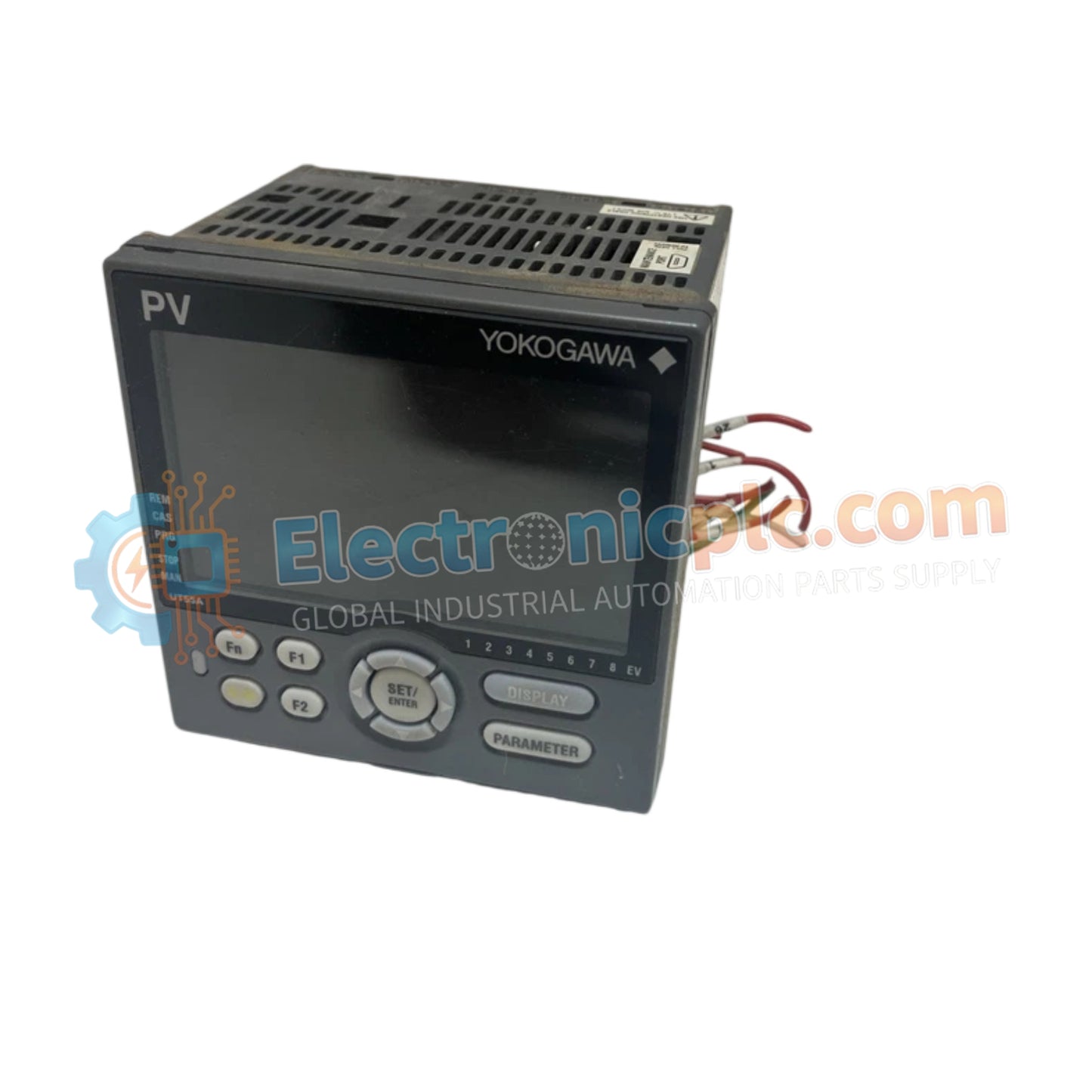
Digital Indicating Controller YOKOGAWA UT55A-040-11-00/LP

Digital Indicating Controller YOKOGAWA UT55A-040-11-00/LP

Configured for precision temperature and process loop management, the YOKOGAWA UT55A-040-11 (UT55A-040-11-00/LP Digital Indicating Controller) provides direct signal processing and setpoint control across distributed instrumentation networks.

Suffix Breakdown & Model...

19 يشاهد الناس هذا الآن

التوافرفي الأوراق المالية

رمز المنتج: UT55A-040-11-00/LP
بائع: Yokogawa

الشحن والإرجاع

توصيل موثوق به في جميع أنحاء العالم

  • شركات الشحن: يتم الشحن عبر DHL أو FedEx أو UPS أو USPS .
  • الشحن: تتم معالجة الطلبات خلال يوم عمل واحد إلى يومين، ويتم شحنها خلال 3 إلى 5 أيام عمل .
  • التتبع: يتم توفير تفاصيل التتبع الكاملة عبر البريد الإلكتروني عند الشحن.

ضمان استرداد الأموال خلال 30 يومًا

  • الضمان: فترة إرجاع لمدة 30 يومًا للمنتجات المتوفرة في المخزون والمغلفة من المصنع.
  • الشروط: يجب أن تكون المنتجات غير مفتوحة وغير مستخدمة وفي عبوتها الأصلية.
  • الأصالة: نضمن أن تكون الأجهزة أصلية 100% .

هل تحتاج إلى مزيد من التفاصيل؟ اقرأ سياسة الشحن وسياسة الاسترداد الكاملة.

الأصالة والضمان

  • ضمان أصلي: نحن نوفر فقط قطع غيار أصلية 100%، جديدة تمامًا، ومغلقة من المصنع .
  • تغطية كاملة: كل مكون مدعوم بضمان شامل لمدة 12 شهرًا من تاريخ الشراء.
  • إمكانية التتبع: جميع المنتجات تأتي مع وثائق المصنع الأصلية والملحقات اللازمة للامتثال الكامل للمعايير الصناعية.

الدعم الفني والتوريد

  • مساعدة الخبراء: يقدم فريقنا الفني استشارات مجانية لمساعدتك في التحقق من التوافق مع أنظمة DCS و PLC.
  • مصادر القطع النادرة: متخصصون في المكونات القديمة والتي يصعب العثور عليها من Allen-Bradley و Siemens و ABB و HIMA وغيرها.
  • للاستفسارات المتعلقة بالكميات الكبيرة: تواصلوا معنا على pambo@5gplc.com للحصول على أسعار الكميات الكبيرة أو عروض أسعار المشاريع المخصصة.
عرض تفاصيل المنتج الكاملة

Configured for precision temperature and process loop management, the YOKOGAWA UT55A-040-11 (UT55A-040-11-00/LP Digital Indicating Controller) provides direct signal processing and setpoint control across distributed instrumentation networks.

Suffix Breakdown & Model Matrix

  • UT55A: Base model for 1/4 DIN digital indicating controller.
  • -040: Specifies hardware configuration including standard control outputs and remote auxiliary analog input support.
  • -11: Defines internal I/O mapping and power supply voltage interface.
  • -00/LP: Designates standard bezel finish and factory software/logic customization level.

Hardware Specifications

Parameter Specification
Model UT55A-040-11-00/LP
Brand YOKOGAWA
Origin Japan
Weight 1.12kg
Dimensions 1/4 DIN standard form factor
Operating Temp Not specified
Power Consumption 18 VA
Supply Voltage 100-240 VAC, 50/60 Hz
Display 5-digit LCD
Input Configuration Remote auxiliary analog input + 1 digital input

Process Control Instrumentation Connectivity

The controller integrates seamlessly into standard process environments utilizing 4-20 mA HART loop protocol standards for field device communication. It features channel-to-channel isolation to ensure that thermocouple or RTD inputs are protected from common-mode voltage interference. The internal circuitry provides advanced cold junction compensation (CJC) to maintain high-accuracy readings in variable ambient temperature conditions, ensuring stable setpoint execution within DCS instrumentation loops.

Frequently Asked Questions

Q: Does the UT55A support field calibration of the analog inputs?

A: Yes, the unit allows for software-based calibration offsets to correct for sensor lead resistance or thermocouple inaccuracies, provided the controller is in the appropriate configuration mode.

Q: Can this model be integrated into an existing Profibus or Fieldbus network?

A: The base model listed utilizes standard analog/digital I/O; integration into digital fieldbus networks typically requires a specific communication module variant or gateway interface.

Field Installation Guidelines

  • Verify the 1/4 DIN cutout dimensions on the control panel to ensure a secure mechanical fit and effective seal for the bezel.
  • Use shielded, twisted-pair cabling for all analog input signals to minimize electromagnetic interference (EMI) and signal noise.
  • Ensure the 100-240 VAC power source is stable and isolated from large inductive loads, such as contactors or motors, to prevent voltage transients.
  • Terminate all sensor leads according to the wiring diagram on the housing to avoid ground loops, particularly when using grounded thermocouples.
  • Confirm that the auxiliary analog input is configured for the correct signal range (voltage or current) in the software menu before applying process signals.