سلة التسوق الخاصة بي
0 عنصرًا
قطع غيار أصلية للأتمتة | توصيل سريع عالمي | ضمان لمدة 12 شهرًا — [احصل على عرض سعر]

Configured for high-density command execution within STARDOM FCN/FCJ autonomous controller platforms, the YOKOGAWA NFDV557-S00 S2 (NFDV557 Digital Output Module) provides direct physical execution of discrete control signals for field-side relays,...
التوافر: في الأوراق المالية
توصيل موثوق به في جميع أنحاء العالم
ضمان استرداد الأموال خلال 30 يومًا
هل تحتاج إلى مزيد من التفاصيل؟ اقرأ سياسة الشحن وسياسة الاسترداد الكاملة.


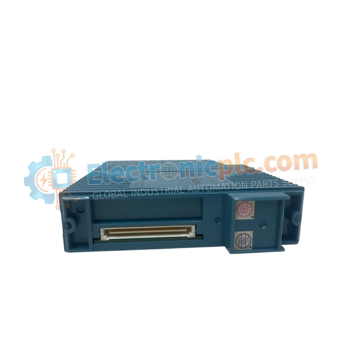
Configured for high-density command execution within STARDOM FCN/FCJ autonomous controller platforms, the YOKOGAWA NFDV557-S00 S2 (NFDV557 Digital Output Module) provides direct physical execution of discrete control signals for field-side relays, valves, and indicators.
The NFDV557-S00 S2 follows a structured revision control scheme. The -S00 designator identifies the module as a base configuration high-density output unit, while the S2 suffix signifies the second hardware iteration, ensuring full compatibility with updated backplane bus communication protocols and enhanced electromagnetic compliance standards.
| Parameter | Specification |
|---|---|
| Model | NFDV557-S00 S2 |
| Brand | YOKOGAWA |
| Origin | Japan |
| Weight | 0.4 kg |
| Dimensions | 2.2 cm x 12.4 cm x 12.6 cm |
| Operating Temp | 0 deg C to 60 deg C |
| Power Consumption | 5 VDC (backplane, 200 mA) |
| Module Type | Digital Output Module |
| Output Type | Discrete signal (relay or transistor drive) |
The NFDV557-S00 S2 incorporates internal galvanic isolation to decouple the controller backplane from the field-side electrical environment. This design is required to suppress common-mode noise and prevent electrical transients—such as inductive kickback from solenoid valves—from propagating back to the FCN/FCJ controller logic. In the event of a system-level fault or loss of communication, the module supports fail-safe state execution, ensuring that digital outputs transition to a predefined safe state to prevent hazardous process conditions.
Q: Can the NFDV557-S00 S2 drive high-current loads directly?
A: No. The output stages are designed for logic-level or pilot-duty switching. High-current loads must be interfaced via external interposing relays to prevent thermal damage to the internal module drivers.
Q: Is this module compatible with hot-swapping procedures?
A: Hot-swapping is supported within the STARDOM architecture, provided the system is configured to handle module state changes. Always verify that the process is in a safe condition before removing the module to avoid unintended field device actuation.


