سلة التسوق الخاصة بي
0 عنصرًا
قطع غيار أصلية للأتمتة | توصيل سريع عالمي | ضمان لمدة 12 شهرًا — [احصل على عرض سعر]

The Yokogawa EBS11-11, also cataloged as the EBS11-11 Bus Interface Module, operates as a dedicated hardware component for S2 bus protocol data exchange within control system network platforms. This module...
التوافر: الكمية المتبقية: 99
توصيل موثوق به في جميع أنحاء العالم
ضمان استرداد الأموال خلال 30 يومًا
هل تحتاج إلى مزيد من التفاصيل؟ اقرأ سياسة الشحن وسياسة الاسترداد الكاملة.


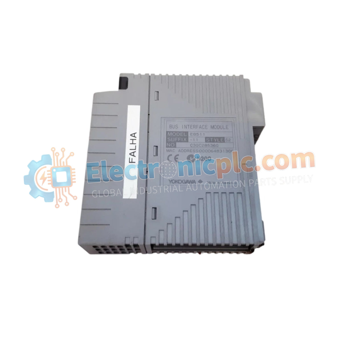
The Yokogawa EBS11-11, also cataloged as the EBS11-11 Bus Interface Module, operates as a dedicated hardware component for S2 bus protocol data exchange within control system network platforms. This module provides the physical and electrical connectivity required to facilitate communication between field instruments and host controllers, maintaining data integrity in demanding industrial environments.
| Parameter | Specification |
|---|---|
| Model | EBS11-11 |
| Brand | Yokogawa |
| Origin | Japan |
| Weight | 0.3 kg |
| Dimensions | 2.5 cm x 12.7 cm x 12.7 cm |
| Operating Temp | -40 to +85 deg C |
| Power Consumption | 1.2 A (Max Input Current) |
| Input Voltage Range | 10 to 30 V DC |
| Nominal Input Voltage | 24 V DC |
| Output Voltage Range | 0 to 10 V DC |
| Nominal Output Voltage | 5 V DC |
| Maximum Output Current | 0.5 A |
The EBS11-11 module handles high-bandwidth process data through dedicated S2 bus protocol integration within the control architecture. Internal circuitry ensures signal integrity by utilizing channel-to-channel isolation, which prevents ground loops and minimizes common-mode interference in industrial electrical environments. The module manages the conversion of field signals into normalized digital values, supporting data synchronization across the controller network. Cold junction compensation (CJC) is provided via integrated algorithms for connected sensor input modules, maintaining measurement precision across distributed sensor chains.
Q: Does the EBS11-11 support hot-swapping during active system operation?
A: No, this module does not support hot-swapping. The specific station must be powered down or placed in a verified maintenance mode prior to module extraction or insertion to prevent damage to the backplane connectors or data corruption on the S2 bus.
Q: How is the module grounded to the chassis?
A: Proper grounding is established through the front-panel retaining screws, which create a low-impedance path to the rack chassis ground. Ensure these are fully tightened to maintain electromagnetic compatibility (EMC) standards.


