سلة التسوق الخاصة بي
0 عنصرًا
قطع غيار أصلية للأتمتة | توصيل سريع عالمي | ضمان لمدة 12 شهرًا — [احصل على عرض سعر]

Configured for high-speed data orchestration within Yokogawa control networks, the YOKOGAWA EC401-51 (EC401-51 ESB Bus Coupler Module) provides direct physical signal transmission and protocol management between Field Control Units (FCUs)...
التوافر: الكمية المتبقية: 99
توصيل موثوق به في جميع أنحاء العالم
ضمان استرداد الأموال خلال 30 يومًا
هل تحتاج إلى مزيد من التفاصيل؟ اقرأ سياسة الشحن وسياسة الاسترداد الكاملة.


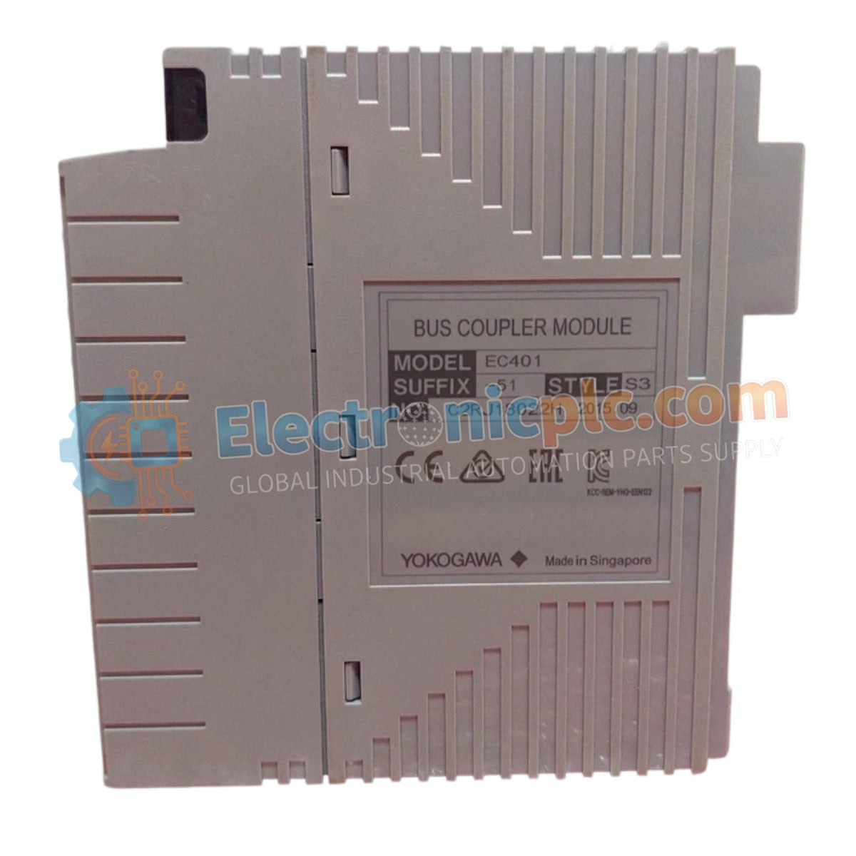
Configured for high-speed data orchestration within Yokogawa control networks, the YOKOGAWA EC401-51 (EC401-51 ESB Bus Coupler Module) provides direct physical signal transmission and protocol management between Field Control Units (FCUs) and downstream I/O node units. This hardware component serves as the primary gateway utilized to execute I/O synchronization across distributed control platforms.
| Parameter | Specification |
|---|---|
| Model | EC401-51 |
| Brand | Yokogawa |
| Origin | Japan |
| Weight | 0.5kg |
| Dimensions | Standard rack-mount module form factor |
| Operating Temp | Standard industrial ambient range |
| Power Consumption | Nominal DCS backplane power supply |
| Function | ESB bus coupling and I/O node synchronization |
The EC401-51 utilizes the Extended Synchronous Bus (ESB) protocol to ensure deterministic data exchange between the main controller and remote I/O nodes. The module manages the electrical and logical conversion required for high-velocity signal transmission across the bus, minimizing communication latency. With the ISA Standard G3 conformal coating, the internal circuitry is protected against airborne contaminants, ensuring longevity in environments with exposure to corrosive gases.
Q: Does the EC401-51 require specific firmware configuration to interface with legacy node units?
A: The module is designed for backward compatibility with established ESB bus architectures; however, ensure that the FCU firmware revision is current to support the specific bus communication parameters required for the node topology.
Q: How does the G3 coating affect module thermal dissipation?
A: The G3 conformal coating is applied at a thickness that does not impede standard thermal dissipation profiles; however, ensure the module is installed in a cabinet with adequate forced-air ventilation to maintain the operating temperature within the specified limits.


