انتقل إلى معلومات المنتج
1 ل 3

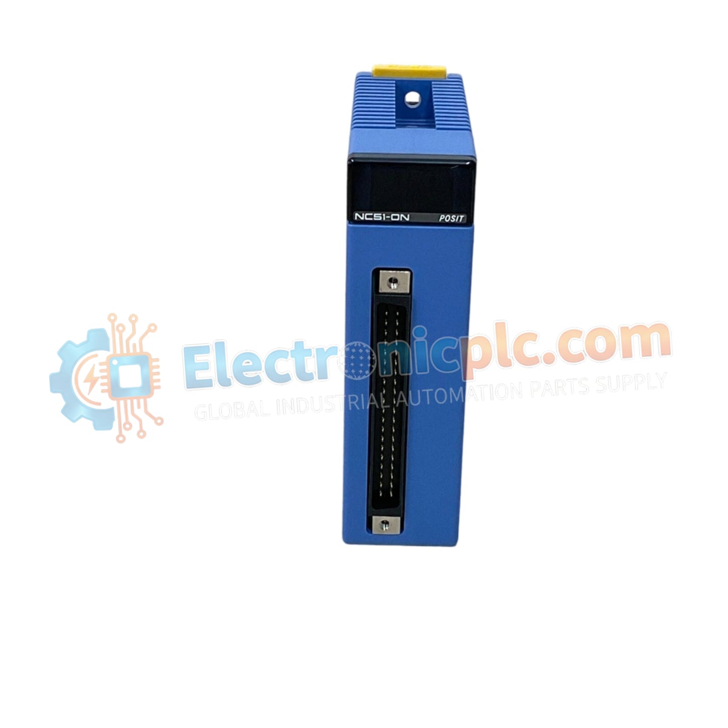
F3NC51-0N Positioning Module YOKOGAWA

F3NC51-0N Positioning Module YOKOGAWA

The YOKOGAWA F3NC51-0N (F3NC51-0N) is a high-performance, single-axis positioning module designed for the FA-M3 sequence CPU series. It provides precise motion control through an analog velocity command interface, bridging the...

29 يشاهد الناس هذا الآن

التوافرفي الأوراق المالية

رمز المنتج: F3NC51-0N
بائع: Yokogawa
Related Series:

الشحن والإرجاع

توصيل موثوق به في جميع أنحاء العالم

  • شركات الشحن: يتم الشحن عبر DHL أو FedEx أو UPS أو USPS .
  • الشحن: تتم معالجة الطلبات خلال يوم عمل واحد إلى يومين، ويتم شحنها خلال 3 إلى 5 أيام عمل .
  • التتبع: يتم توفير تفاصيل التتبع الكاملة عبر البريد الإلكتروني عند الشحن.

ضمان استرداد الأموال خلال 30 يومًا

  • الضمان: فترة إرجاع لمدة 30 يومًا للمنتجات المتوفرة في المخزون والمغلفة من المصنع.
  • الشروط: يجب أن تكون المنتجات غير مفتوحة وغير مستخدمة وفي عبوتها الأصلية.
  • الأصالة: نضمن أن تكون الأجهزة أصلية 100% .

هل تحتاج إلى مزيد من التفاصيل؟ اقرأ سياسة الشحن وسياسة الاسترداد الكاملة.

الأصالة والضمان

  • ضمان أصلي: نحن نوفر فقط قطع غيار أصلية 100%، جديدة تمامًا، ومغلقة من المصنع .
  • تغطية كاملة: كل مكون مدعوم بضمان شامل لمدة 12 شهرًا من تاريخ الشراء.
  • إمكانية التتبع: جميع المنتجات تأتي مع وثائق المصنع الأصلية والملحقات اللازمة للامتثال الكامل للمعايير الصناعية.

الدعم الفني والتوريد

  • مساعدة الخبراء: يقدم فريقنا الفني استشارات مجانية لمساعدتك في التحقق من التوافق مع أنظمة DCS و PLC.
  • مصادر القطع النادرة: متخصصون في المكونات القديمة والتي يصعب العثور عليها من Allen-Bradley و Siemens و ABB و HIMA وغيرها.
  • للاستفسارات المتعلقة بالكميات الكبيرة: تواصلوا معنا على pambo@5gplc.com للحصول على أسعار الكميات الكبيرة أو عروض أسعار المشاريع المخصصة.
عرض تفاصيل المنتج الكاملة

The YOKOGAWA F3NC51-0N (F3NC51-0N) is a high-performance, single-axis positioning module designed for the FA-M3 sequence CPU series. It provides precise motion control through an analog velocity command interface, bridging the gap between digital PLC logic and high-speed servo drive regulation.

Hardware Specifications

Parameter Specification
Model F3NC51-0N
Brand YOKOGAWA
Origin Japan
Weight 0.3kg
Dimensions 28.9 mm x 100 mm x 83.2 mm
Power Consumption 390 mA @ 5 VDC / 10 mA @ 24 VDC
Axis Control 1-Axis
Control Method Semi-closed loop (-10 to +10 V output)
Feedback Interface Incremental (A/B phase) / Absolute encoder
Position Range -134,217,728 to +134,217,727 pulses

Precision Motion Control Architecture

The F3NC51-0N module manages motion by converting high-speed pulse feedback from encoders into a precise -10 V to +10 V analog velocity command. This analog signal allows the module to command servo drives with high resolution, enabling smooth velocity control and dynamic acceleration profiling. The module supports various profiles, including Trapezoidal, Two-stage linear, and S-curve (three-stage), which are critical for minimizing mechanical vibrations during high-speed moves.

Frequently Asked Questions

Q: Does the F3NC51-0N support multi-axis synchronization?

A: Yes, while the module itself controls one axis, multi-axis linear and arc interpolation can be achieved by coordinating multiple modules via the FA-M3 CPU and its system bus, allowing for complex multi-axis motion paths.

Q: Can the module handle high-frequency encoder signals?

A: The module supports incremental encoders with line driver outputs up to a maximum frequency of 2 Mpps (after 4x multiplication), making it suitable for high-resolution positioning tasks.

Field Installation Guidelines

  • Shielding: Ensure all encoder feedback cables and analog command cables are shielded and twisted-pair to minimize electromagnetic interference (EMI), which could lead to position drift or erratic velocity command behavior.
  • Grounding: Bond the shield of the analog cable to the designated signal ground terminal on the module to prevent ground loops between the PLC and the servo driver.
  • Power Supply: Use a stable 5 VDC source for the module logic and a clean 24 VDC source for the I/O signals, ensuring the power supply current capacity exceeds the module's rated consumption.
  • Wiring: Keep signal cables separated from high-current power cables (e.g., motor drive cables) by at least 100-200 mm to prevent induced noise in the analog control signals.
  • Startup: Utilize the 6 ms maximum startup time in the control logic to ensure the module is fully initialized before attempting to issue motion commands to the servo drive.