سلة التسوق الخاصة بي
0 عنصرًا
قطع غيار أصلية للأتمتة | توصيل سريع عالمي | ضمان لمدة 12 شهرًا — [احصل على عرض سعر]

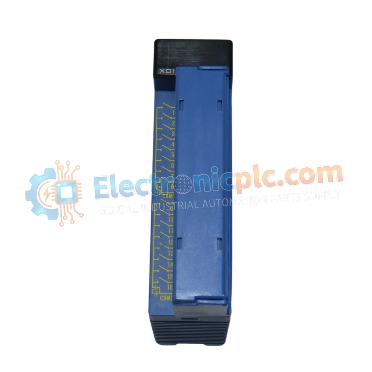
يعمل YOKOGAWA F3XD16-3N، المصنف أيضًا كوحدة الإدخال الرقمي F3XD16، كمكون أجهزة مخصص لاكتساب الإشارات المنفصلة ضمن منصات FA-M3 PLC.
| المعلمة | المواصفات |
|---|
| المعلمة | المواصفات |
|---|---|
| النموذج | F3XD16-3N |
| العلامة التجارية | YOKOGAWA |
| المنشأ | اليابان |
| الوزن | 0.2 كجم |
| الأبعاد | 3.3 سم × 10.2 سم × 8.9 سم |
| درجة حرارة التشغيل | 0 درجة مئوية إلى 55 درجة مئوية |
| استهلاك الطاقة | 65 مللي أمبير (5 فولت تيار مستمر) |
| قنوات الإدخال | 16 |
| جهد الإدخال | 24 فولت تيار مستمر |
| تيار الإدخال | 4.1 مللي أمبير لكل نقطة |
| العزل | مقارن ضوئي |
يستخدم F3XD16-3N ناقل اللوحة الخلفية FA-M3 لتسهيل نقل الإشارة عالي السرعة والمحدد بين مستشعرات الحقل ووحدة المعالجة المركزية لوحدة التحكم. تم تصميم بنية الوحدة للتوسيع الفعال لكثافة المدخلات/المخرجات، مما يسمح بدمج وحدات إدخال متعددة دون المساومة على سرعة اتصال الناقل. يتم توفير عزل المقارن الضوئي لكل قناة من القنوات الـ 16، مما يضمن قمع ضوضاء الوضع المشترك وحماية منطق وحدة التحكم من الفولتية العابرة على مستوى الحقل. يتم دعم توافق وميض البرامج الثابتة للحفاظ على الاتساق مع تكوينات PLC على مستوى النظام.
س: هل يمكن تعديل وقت استجابة الإدخال لمتطلبات تصفية إشارة محددة؟
ج: نعم، وقت استجابة الإدخال قابل للتكوين برمجيًا بين 62.5 ميكرو ثانية و 16 مللي ثانية. وهذا يسمح بتصفية ارتداد التلامس أو الضوضاء عالية التردد من الأجهزة الميدانية الميكانيكية.
س: هل تدعم الوحدة كلاً من تكوينات إدخال المخرج والمصدر؟
ج: نعم، تم تصميم F3XD16-3N لدعم كل من منطق إدخال المخرج والمصدر، مما يوفر مرونة لمتطلبات أسلاك الأجهزة الميدانية المتنوعة ضمن نفس رف FA-M3.