
سلة التسوق الخاصة بي
0 عنصرًا
قطع غيار أصلية للأتمتة | توصيل سريع عالمي | ضمان لمدة 12 شهرًا — [احصل على عرض سعر]

يعمل جهاز Woodward 37532، والذي يُعرف أيضًا باسم وحدة التحكم في مجموعة المولدات easYgen-3100/3200، كمكون أجهزة مخصص لتنفيذ فشل الشبكة الرئيسي التلقائي وإدارة المحرك والمولد داخل شبكات التحكم من سلسلة...
التوافر: الكمية المتبقية: 10
توصيل موثوق به في جميع أنحاء العالم
ضمان استرداد الأموال خلال 30 يومًا
هل تحتاج إلى مزيد من التفاصيل؟ اقرأ سياسة الشحن وسياسة الاسترداد الكاملة.


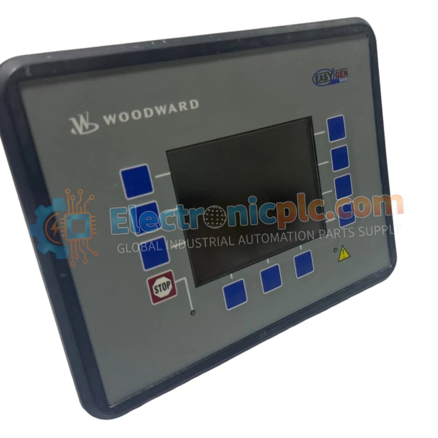
يعمل جهاز Woodward 37532، والذي يُعرف أيضًا باسم وحدة التحكم في مجموعة المولدات easYgen-3100/3200، كمكون أجهزة مخصص لتنفيذ فشل الشبكة الرئيسي التلقائي وإدارة المحرك والمولد داخل شبكات التحكم من سلسلة easYgen-3000.
| المعلمة | المواصفات |
|---|---|
| الموديل | 37532 |
| العلامة التجارية | Woodward |
| المنشأ | الولايات المتحدة الأمريكية |
| الوزن | 1.2 كجم |
| الأبعاد | 196 مم × 146 مم × 45 مم |
| درجة حرارة التشغيل | -40 إلى +70 درجة مئوية (-40 إلى +158 درجة فهرنهايت) |
| استهلاك الطاقة | نطاق تشغيل إدخال 8-35 VDC |
| الشاشة | شاشة LCD بإضاءة خلفية 128 × 64 بكسل |
| واجهات الاتصال | ناقل CAN (J1939، Modbus RTU)، RS-232، RS-485 |
| المداخل التناظرية | 4 مداخل (0-10 VDC، 4-20 مللي أمبير) |
| المداخل الرقمية | 6 مداخل قابلة للتهيئة |
| مخرجات الريليه | 4 مخرجات قابلة للتهيئة |
| تنظيم السرعة | +/-0.1% من عدم الحمل إلى الحمل الكامل |
| تنظيم الجهد | +/-0.5% من الجهد المقنن |
| التركيب | خيارات تركيب على سكة DIN أو لوحة |
يستخدم Woodward 37532 حلقات معالجة داخلية عالية السرعة لتقديم استجابة دقيقة لحلقة ملاحظات المشغل أثناء المزامنة التلقائية ومشاركة الحمل بين المولدات المتوازية. من خلال مراقبة تنظيم السرعة ضمن +/-0.1% وتنظيم الجهد ضمن +/-0.5% عبر مجموعات المولدات المتصلة، يحسب جهاز التحكم فروق الحمل ويضبط واجهات الخانق والإثارة وفقًا لذلك. يضمن الاتصال عبر ناقل CAN المتكامل (J1939، Modbus RTU) والشبكات التسلسلية إجراءات تحكم محددة، مما يحافظ على استقرار اقتران الشبكة وتردد النظام تحت طلبات الأحمال المتغيرة.
س: ما هو نطاق طاقة إدخال التيار المستمر المدعوم لوحدة التحكم Woodward 37532؟
ج: تقبل الوحدة مصدر طاقة إدخال إضافي يعمل بين 8 VDC و 35 VDC.
س: ما هي بروتوكولات الاتصالات التسلسلية والناقل المدمجة أصلاً في الوحدة؟
ج: تحتوي الوحدة على واجهات ناقل CAN تدعم بروتوكولات J1939 و Modbus RTU، بالإضافة إلى منافذ RS-232 و RS-485 لتكامل النظام.
س: كيف تتفاعل وحدة التحكم مع المستشعرات الخارجية وعناصر التحكم؟
ج: يوفر الجهاز 4 مدخلات تناظرية قابلة للتهيئة (0-10 VDC أو 4-20 مللي أمبير)، و 6 مدخلات رقمية قابلة للتهيئة، و 4 مخرجات ريليه قابلة للتهيئة لتنفيذ التحكم المنفصل.


