
سلة التسوق الخاصة بي
0 عنصرًا
قطع غيار أصلية للأتمتة | توصيل سريع عالمي | ضمان لمدة 12 شهرًا — [احصل على عرض سعر]

تم تكوين YOKOGAWA KS1-07*B (كابل إشارة KS1) للربط البيني للإشارة عالية الكثافة، ويوفر تنفيذًا ماديًا/كهربائيًا مباشرًا لنقل البيانات بين لوحات الأطراف الميدانية وتجميعات وحدة الإدخال/الإخراج داخل معماريات التحكم من سلسلة CENTUM. يستخدم...
التوافر: في الأوراق المالية
توصيل موثوق به في جميع أنحاء العالم
ضمان استرداد الأموال خلال 30 يومًا
هل تحتاج إلى مزيد من التفاصيل؟ اقرأ سياسة الشحن وسياسة الاسترداد الكاملة.
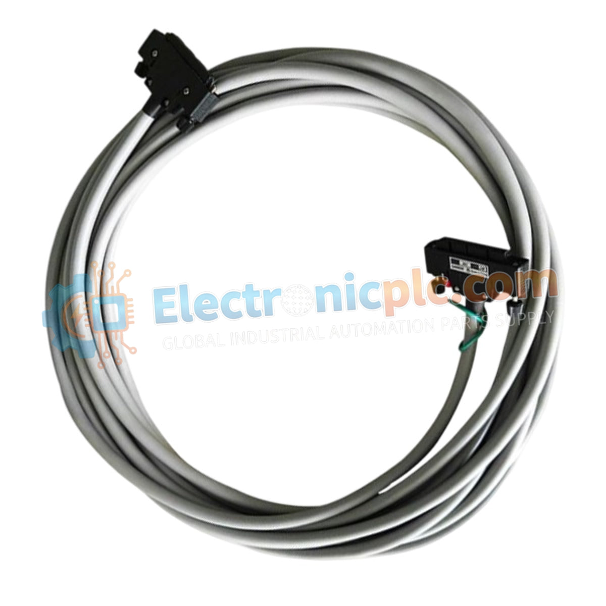
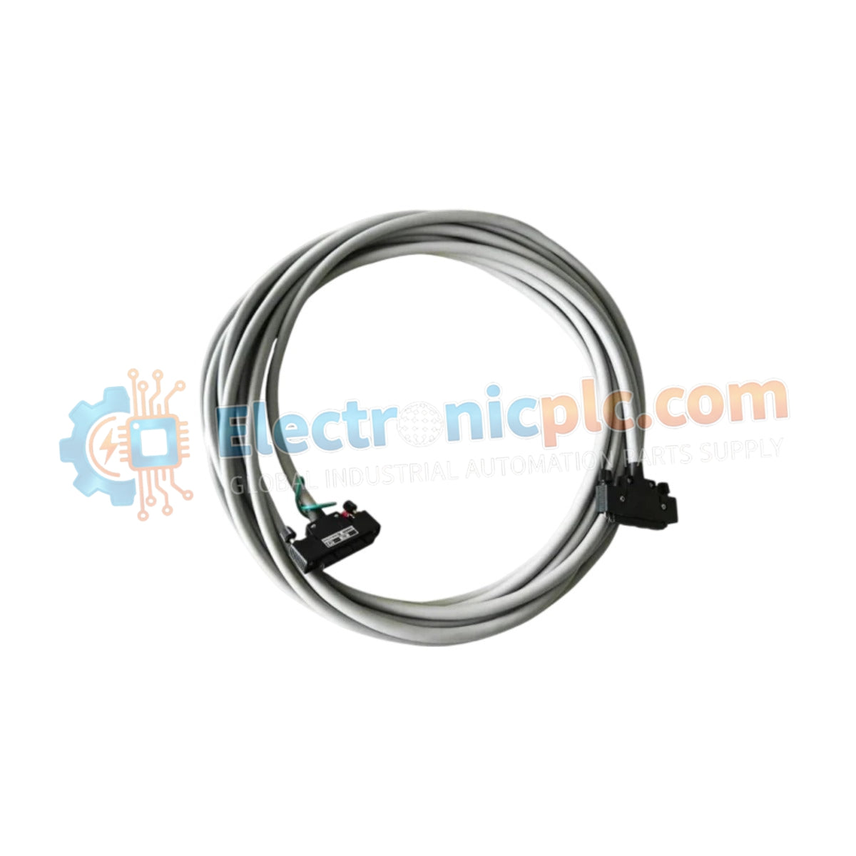
تم تكوين YOKOGAWA KS1-07*B (كابل إشارة KS1) للربط البيني للإشارة عالية الكثافة، ويوفر تنفيذًا ماديًا/كهربائيًا مباشرًا لنقل البيانات بين لوحات الأطراف الميدانية وتجميعات وحدة الإدخال/الإخراج داخل معماريات التحكم من سلسلة CENTUM. يستخدم تجميع الكابل هذا واجهة من 40 دبوسًا إلى 40 دبوسًا للحفاظ على مسارات إشارة حتمية عبر نظام التحكم الموزع.
يتم تعريف KS1-07*B من خلال سمات التكوين التالية:
KS1: تسمية النموذج الأساسي لكابل الإشارة متعدد الدبابيس.
07: يحدد طول الكابل 7 أمتار.
*B: يشير إلى التصميم من النمط B، مما يضمن التوافق مع معايير واجهة سلسلة CENTUM VP وCS الحالية.
| المعلمة | المواصفات |
| النموذج | KS1-07*B |
| العلامة التجارية | YOKOGAWA |
| بلد المنشأ | اليابان |
| الوزن | 0.9 كجم |
| الأبعاد | 25.4 سم × 5.1 سم × 38.1 سم |
| تكوين الدبابيس | 40 دبوسًا إلى 40 دبوسًا |
| نوع الكابل | كابل إشارة متعدد النوى |
| درجة حرارة التشغيل | -20 درجة مئوية إلى 70 درجة مئوية |
تم تصميم KS1-07*B لتسهيل تبادل البيانات الموثوق به من خلال الحفاظ على الأداء الكهربائي المتسق عبر واجهة 40 دبوسًا. يدعم هذا الاتصال عالي الكثافة انتشار الإشارات التناظرية والرقمية، مما يضمن بقاء سعة الإشارة ضمن المعايير المحددة بدقة المطلوبة لشبكات CENTUM VP المقاومة للأخطاء. يتميز تجميع الكابل بتدريع مدمج للتخفيف من مخاطر التداخل الكهرومغناطيسي (EMI) في بيئات الخزانات الصناعية عالية الضوضاء، مما يحافظ على دقة الإشارة لأجهزة التحكم في العمليات.
س: هل هذا الكابل مناسب للاستخدام في المناطق ذات الاهتزازات العالية؟
ج: نعم، تم تصميم موصلات الكابل لتثبيت آمن في اللوحات الخلفية للوحدات ولوحات الأطراف، مما يوفر احتفاظًا ميكانيكيًا يقاوم التراخي الناتج عن أنماط الاهتزاز الصناعية. تأكد من أن آليات قفل الموصل متصلة بالكامل عند التثبيت.
س: هل يمكن توصيل كبلات KS1 متعددة على التوالي لزيادة الطول؟
ج: لا، تم تصميم مجموعة كابل KS1 للتوصيلات من نقطة إلى نقطة بين لوحة طرفية ووحدة إدخال/إخراج. لا يوصى بتمديد المسافة عبر التوصيل المتسلسل لأنه يزيد من مقاومة التلامس واحتمال تدهور الإشارة.
افحص موصلات 40 دبوسًا بحثًا عن دبابيس مثنية أو مؤكسدة قبل التثبيت. يمكن أن يؤدي اتصال الدبوس المعرض للخطر إلى أخطاء متقطعة في اتصال الإدخال/الإخراج أو فقدان الإشارة.
عند توجيه الكابل، حافظ على نصف قطر انحناء أدنى كما هو محدد بواسطة هيكل الكابل لمنع تعب الموصل الداخلي أو تلف الدرع.
حافظ على فصل كابل الإشارة ماديًا عن خطوط الطاقة عالية الجهد وكابلات محرك التيار المتردد لتقليل اقتران الضوضاء الحثية.
قم بمحاذاة الموصل عموديًا مع المنفذ الموجود على وحدة الإدخال/الإخراج أو لوحة الأطراف وادفع بقوة حتى يتم تثبيت آلية القفل بالكامل.
قم بتثبيت الكابل بهيكل الخزانة باستخدام روابط الكابلات أو قنوات الإدارة، مع التأكد من أن الموصل ليس تحت توتر أو إجهاد مادي.


