سلة التسوق الخاصة بي
0 عنصرًا
قطع غيار أصلية للأتمتة | توصيل سريع عالمي | ضمان لمدة 12 شهرًا — [احصل على عرض سعر]

Configured for high-density signal transmission in DCS instrumentation, the YOKOGAWA KS1-15*B (KS1-15*B Signal Cable) provides direct physical signal interconnectivity between field terminal boards and I/O modules. This hardware component manages...
التوافر: الكمية المتبقية: 99
توصيل موثوق به في جميع أنحاء العالم
ضمان استرداد الأموال خلال 30 يومًا
هل تحتاج إلى مزيد من التفاصيل؟ اقرأ سياسة الشحن وسياسة الاسترداد الكاملة.

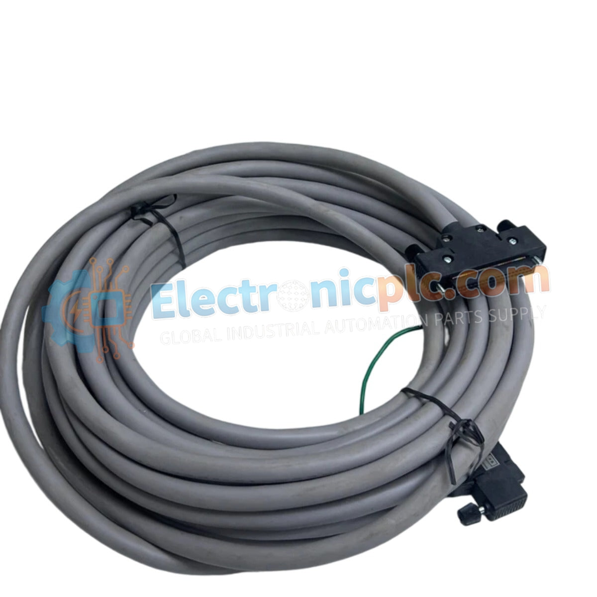
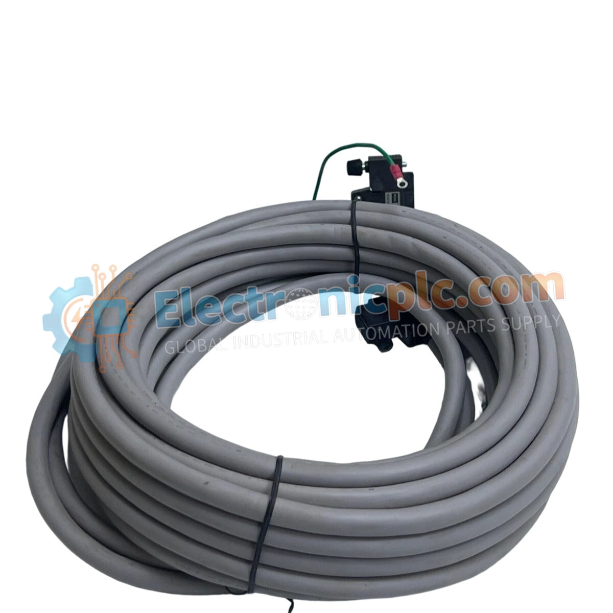
Configured for high-density signal transmission in DCS instrumentation, the YOKOGAWA KS1-15*B (KS1-15*B Signal Cable) provides direct physical signal interconnectivity between field terminal boards and I/O modules. This hardware component manages multi-channel data path integrity across distributed control system platforms.
| Parameter | Specification |
|---|---|
| Model | KS1-15*B |
| Brand | Yokogawa |
| Origin | Japan |
| Weight | 1.67kg |
| Dimensions | 15 meters length |
| Operating Temp | -20 deg C to +70 deg C |
| Power Consumption | Not applicable (Passive transmission media) |
| Connector Type | 40-pin to 40-pin interface |
| Shielding | Foil and braid EMI protection |
The KS1-15*B utilizes copper conductors and integrated shielding to maintain signal fidelity in industrial environments prone to electromagnetic interference (EMI). The 40-pin connector architecture allows for bulk signal transition, reducing the wiring complexity typically associated with high-density I/O clusters. The PVC insulation ensures flexibility and protection against common environmental factors within control cabinets and cable trays.
Q: Can the 15-meter length affect the voltage drop of analog signal loops?
A: Yes, signal loops at lengths of 15 meters must account for the conductor resistance. Ensure the total loop impedance remains within the transmitter and I/O module specifications to maintain accurate 4-20 mA loop operation.
Q: Is the shield drain wire intended for grounding at both ends?
A: Best practice typically involves grounding the shield at a single reference point—usually the cabinet ground bus—to prevent the formation of ground loops that could inject electrical noise into the signal path.


