انتقل إلى معلومات المنتج
1 ل 3

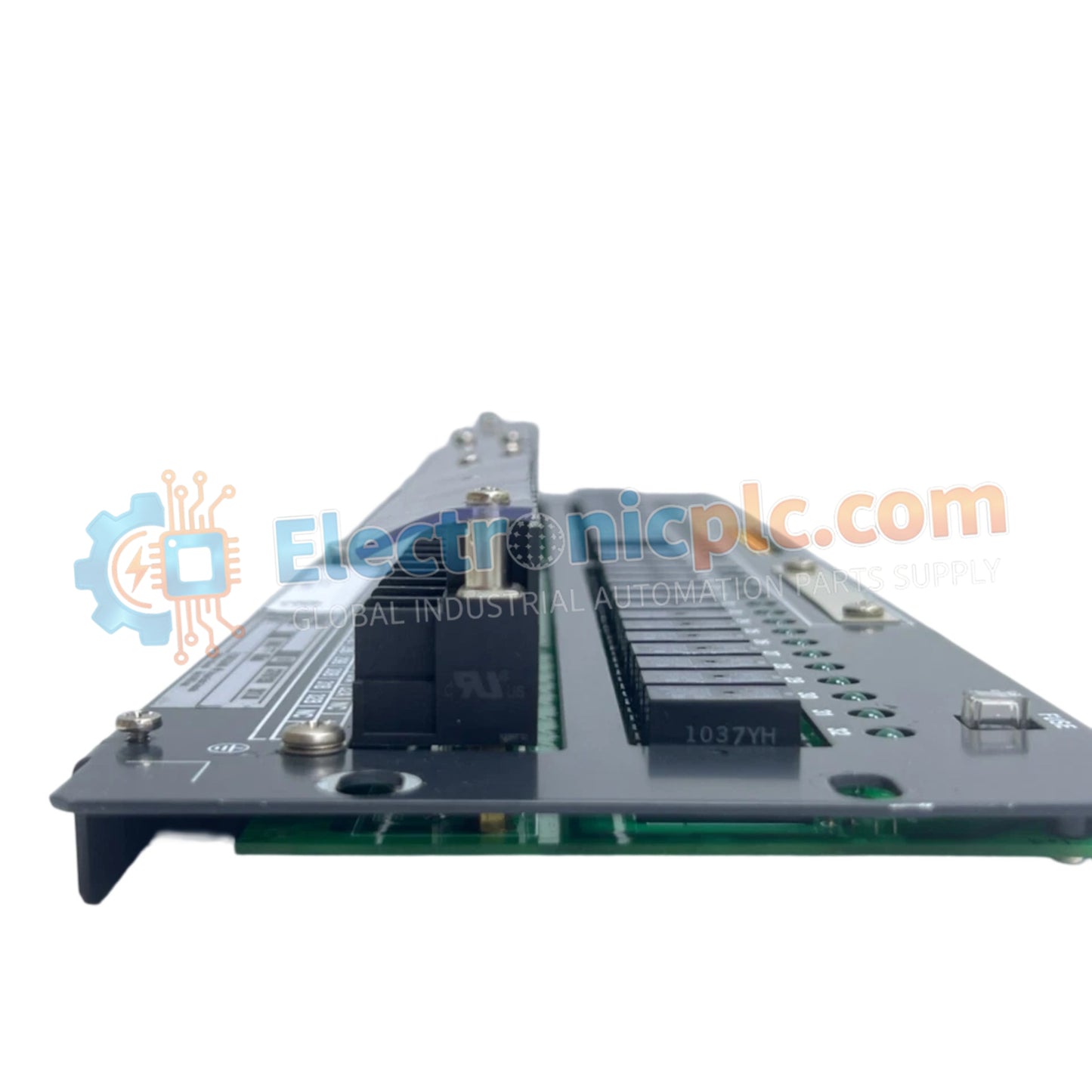
Mechanical Relay Output Board Yokogawa ARM55C-000

Mechanical Relay Output Board Yokogawa ARM55C-000

Configured for high-density digital signal switching in CENTUM VP systems, the Yokogawa ARM55C-000 (ARM55C Mechanical Relay Output Board) provides direct physical and electrical execution of dry-contact output switching for field...

28 يشاهد الناس هذا الآن

التوافرفي الأوراق المالية

رمز المنتج: ARM55C-000
بائع: Yokogawa

الشحن والإرجاع

توصيل موثوق به في جميع أنحاء العالم

  • شركات الشحن: يتم الشحن عبر DHL أو FedEx أو UPS أو USPS .
  • الشحن: تتم معالجة الطلبات خلال يوم عمل واحد إلى يومين، ويتم شحنها خلال 3 إلى 5 أيام عمل .
  • التتبع: يتم توفير تفاصيل التتبع الكاملة عبر البريد الإلكتروني عند الشحن.

ضمان استرداد الأموال خلال 30 يومًا

  • الضمان: فترة إرجاع لمدة 30 يومًا للمنتجات المتوفرة في المخزون والمغلفة من المصنع.
  • الشروط: يجب أن تكون المنتجات غير مفتوحة وغير مستخدمة وفي عبوتها الأصلية.
  • الأصالة: نضمن أن تكون الأجهزة أصلية 100% .

هل تحتاج إلى مزيد من التفاصيل؟ اقرأ سياسة الشحن وسياسة الاسترداد الكاملة.

الأصالة والضمان

  • ضمان أصلي: نحن نوفر فقط قطع غيار أصلية 100%، جديدة تمامًا، ومغلقة من المصنع .
  • تغطية كاملة: كل مكون مدعوم بضمان شامل لمدة 12 شهرًا من تاريخ الشراء.
  • إمكانية التتبع: جميع المنتجات تأتي مع وثائق المصنع الأصلية والملحقات اللازمة للامتثال الكامل للمعايير الصناعية.

الدعم الفني والتوريد

  • مساعدة الخبراء: يقدم فريقنا الفني استشارات مجانية لمساعدتك في التحقق من التوافق مع أنظمة DCS و PLC.
  • مصادر القطع النادرة: متخصصون في المكونات القديمة والتي يصعب العثور عليها من Allen-Bradley و Siemens و ABB و HIMA وغيرها.
  • للاستفسارات المتعلقة بالكميات الكبيرة: تواصلوا معنا على pambo@5gplc.com للحصول على أسعار الكميات الكبيرة أو عروض أسعار المشاريع المخصصة.
عرض تفاصيل المنتج الكاملة

Configured for high-density digital signal switching in CENTUM VP systems, the Yokogawa ARM55C-000 (ARM55C Mechanical Relay Output Board) provides direct physical and electrical execution of dry-contact output switching for field devices.

Suffix Breakdown & Model Matrix

  • ARM55C: Base series designation for 32-channel mechanical relay output boards.
  • 000: Configuration code indicating standard output density and logic arrangement.

Hardware Specifications

Parameter Specification
Model ARM55C-000
Brand Yokogawa
Origin Japan
Weight 2.2 kg
Dimensions 19-inch rack-mount standard
Operating Temp 0 deg C to 50 deg C
Power Consumption 24 V DC (0.85 A maximum)
Output Channels 32 dry-contact relays (NO/NC)
Max Load 250 V AC/30 V DC @ 2 A; 125 V DC @ 0.1 A
Min Load 5 V DC @ 10 mA

Relay Logic and Galvanic Isolation

The ARM55C-000 utilizes mechanical relays to provide complete galvanic isolation between the low-voltage DCS logic circuits and the field-side load circuits. This isolation prevents high-voltage transients from propagating back to the CENTUM VP backplane. Each channel is field-configurable for Normally Open (NO) or Normally Closed (NC) operation, allowing the board to execute fail-safe state logic based on specific process safety requirements. The dielectric strength of 2 kV between field terminals and case ensures robust protection against common industrial electrical faults.

Frequently Asked Questions

Q: Can the ARM55C-000 be used for high-speed pulse outputs?

A: No. As a mechanical relay board, the switching speed is limited by the mechanical travel time of the relay contacts. It is designed for low-speed digital control, such as driving solenoid valves or contactor coils, and is not suitable for high-frequency pulse width modulation (PWM) or rapid pulsing.

Q: What is the minimum load requirement to prevent contact oxidation?

A: To maintain reliable contact closure over time, each channel requires a minimum load of 5 V DC at 10 mA. Operating below this threshold can lead to the formation of insulating oxide layers on the relay contacts, resulting in intermittent operation.

Field Installation Guidelines

  • Rack Mounting: Secure the unit into a 19-inch rack using M3.5 screws. Ensure the enclosure provides sufficient grounding to the cabinet frame to utilize the board's dielectric strength ratings effectively.
  • Wiring Segregation: Maintain physical separation between relay output wiring (carrying AC/DC load power) and sensitive low-voltage signal lines. Induced EMI can cause false triggers if relay lines are bundled with analog signal cables.
  • Surge Suppression: When switching inductive loads (such as motor contactors or solenoid coils), install an external flyback diode (for DC) or an RC snubber network (for AC) across the load. This prevents back-EMF from arcing across the relay contacts, which significantly extends contact service life.
  • Thermal Management: Ensure the cabinet environment remains between 0 and 50 deg C. Since mechanical relays dissipate heat during continuous engagement, maintain adequate spacing for convection cooling to prevent ambient temperature escalation.