
سلة التسوق الخاصة بي
0 عنصرًا
قطع غيار أصلية للأتمتة | توصيل سريع عالمي | ضمان لمدة 12 شهرًا — [احصل على عرض سعر]

تم تكوينه لاكتساب الإشارات عالية الكثافة في منصات التحكم الصناعية، يوفرYOKOGAWA NFA143-H50/A4AS0 (NFA143 وحدة الإدخال التناظرية) تنفيذًا فيزيائيًا/كهربائيًا مباشرًا لحلقات المعالجة 4-20 مللي أمبير. تقوم هذه المكونة...
التوافر: في الأوراق المالية
توصيل موثوق به في جميع أنحاء العالم
ضمان استرداد الأموال خلال 30 يومًا
هل تحتاج إلى مزيد من التفاصيل؟ اقرأ سياسة الشحن وسياسة الاسترداد الكاملة.

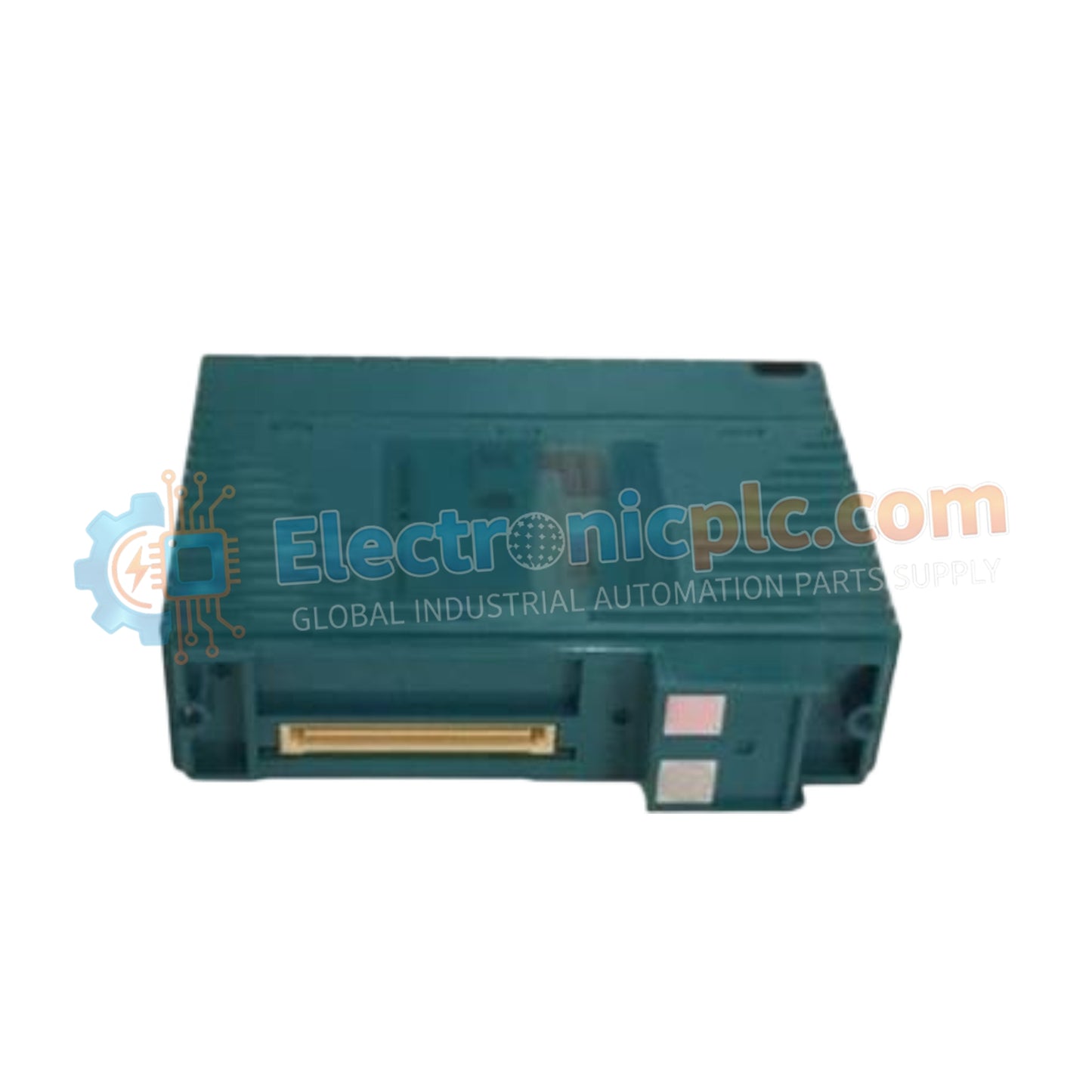
تم تكوينه لاكتساب الإشارات عالية الكثافة في منصات التحكم الصناعية، يوفرYOKOGAWA NFA143-H50/A4AS0 (NFA143 وحدة الإدخال التناظرية) تنفيذًا فيزيائيًا/كهربائيًا مباشرًا لحلقات المعالجة 4-20 مللي أمبير. تقوم هذه المكونة الصلبة بمعالجة 16 قناة معزولة، مما يضمن اكتساب البيانات بشكل حتمي وسلامة إشارة قوية عبر أنظمة التحكم الموزعة.
يتم تعريف NFA143-H50/A4AS0 بواسطة سمات التكوين التالية:
NFA143: تحديد النموذج الأساسي لوحدة الإدخال التناظرية ذات 16 قناة.
H50: يحدد التكوين التشغيلي القياسي لأنظمة التحكم في العمليات من Yokogawa.
A4AS0: يحدد واجهة الطرفية المحددة ومستوى التصلب البيئي للتجميع.
| المعلمة | المواصفات |
| النموذج | NFA143-H50/A4AS0 |
| الماركة | YOKOGAWA |
| الأصل | اليابان |
| الوزن | 0.3 كجم |
| الأبعاد | حاوية وحدة قياسية |
| درجة حرارة التشغيل | 0 درجة مئوية إلى 60 درجة مئوية |
| استهلاك الطاقة | 230 مللي أمبير (5 فولت تيار مستمر)، 540 مللي أمبير (24 فولت تيار مستمر) |
| قنوات الإدخال | 16 معزولة |
| دورة تحديث البيانات | 10 مللي ثانية |
| الدقة | +/- 0.1% من المقياس الكامل |
تم تحسين NFA143-H50/A4AS0 للاتصال ببروتوكول حلقة HART 4-20 مللي أمبير. يتميز بعزل قناة إلى قناة وجهد تحمل عازل يبلغ 1500 فولت تيار متردد، مما يضمن عدم تدهور الضوضاء الكهربائية في الوضع المشترك لدقة الإشارة في خزانات الأجهزة متعددة الحلقات. تستخدم المكونة الصلبة استشعارًا دقيقًا للتيار للتخفيف من الانجراف الحراري، مما يحافظ على الاستقرار ضمن ±0.01% لكل درجة مئوية، وهو أمر ضروري لأداء تحكم ثابت.
س: هل يمكن لـ NFA143-H50/A4AS0 دعم أجهزة المجال التي تتطلب طاقة خارجية؟ج: تم تصميم الوحدة لقبول إشارات التيار 4-20 مللي أمبير. بالنسبة لأجهزة المجال التي تتطلب طاقة خارجية، تأكد من أن أسلاك الحلقة تتضمن مصدر طاقة مناسبًا وأن استشعار التيار يتم بشكل تسلسلي داخل الحلقة.
س: كيف تتعامل الوحدة مع حالات التيار الزائد؟ج: يتضمن NFA143-H50/A4AS0 حماية مدمجة من التيار الزائد لحماية دوائر تحويل A/D الداخلية من تيارات الأعطال التي تتجاوز الحد الأقصى للإدخال البالغ 24 مللي أمبير.
تحقق من أن طاقة اللوحة الخلفية للنظام ضمن النطاق المحدد من 24.0 فولت تيار مستمر إلى 25.5 فولت تيار مستمر قبل إدخال الوحدة لمنع انخفاض محتمل في جهد المنطق.
قم بإنهاء إشارات 4-20 مللي أمبير باستخدام كابلات مزدوجة مجدولة ومحمية. قم بتأريض الدرع عند نقطة دخول الخزانة إلى ناقل التأريض للأجهزة لتقليل التعرض للتداخل الكهرومغناطيسي.
افحص وصلات الأطراف للتأكد من الأمان الميكانيكي؛ يمكن أن تؤدي الوصلات الفضفاضة في حلقات التيار إلى إدخال ضوضاء إشارة كبيرة وأخطاء قياس متقطعة.
حافظ على مسافة خلوص أدنى لتدفق الهواء المحيط حول غلاف الوحدة، حيث أن استهلاك التيار العالي (540 مللي أمبير عند 24 فولت تيار مستمر) قد يساهم في توليد حرارة موضعية في الخزانات عالية الكثافة.
بعد التثبيت، قم بإجراء فحص تشخيصي للحلقة باستخدام برنامج وحدة تحكم DCS للتحقق من أن القيم الرقمية تتوافق بدقة مع مستويات التيار الميداني المقاسة.

