انتقل إلى معلومات المنتج
1 ل 2

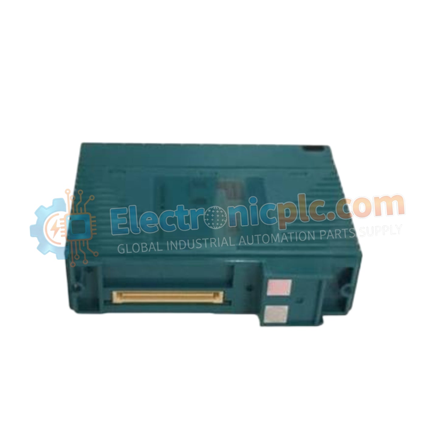
NFAI143-H50/CCC01 Analog Input Module Yokogawa

NFAI143-H50/CCC01 Analog Input Module Yokogawa

Configured for high-density signal acquisition in CENTUM VP control networks, the Yokogawa NFAI143-H50/CCC01 (NFAI143-H50 Analog Input Module) provides direct physical/electrical execution of 16-channel 4-20 mA current loop monitoring.

Suffix Breakdown...

24 يشاهد الناس هذا الآن

التوافرفي الأوراق المالية

رمز المنتج: NFAI143-H50/CCC01
بائع: Yokogawa
Related Series:

الشحن والإرجاع

توصيل موثوق به في جميع أنحاء العالم

  • شركات الشحن: يتم الشحن عبر DHL أو FedEx أو UPS أو USPS .
  • الشحن: تتم معالجة الطلبات خلال يوم عمل واحد إلى يومين، ويتم شحنها خلال 3 إلى 5 أيام عمل .
  • التتبع: يتم توفير تفاصيل التتبع الكاملة عبر البريد الإلكتروني عند الشحن.

ضمان استرداد الأموال خلال 30 يومًا

  • الضمان: فترة إرجاع لمدة 30 يومًا للمنتجات المتوفرة في المخزون والمغلفة من المصنع.
  • الشروط: يجب أن تكون المنتجات غير مفتوحة وغير مستخدمة وفي عبوتها الأصلية.
  • الأصالة: نضمن أن تكون الأجهزة أصلية 100% .

هل تحتاج إلى مزيد من التفاصيل؟ اقرأ سياسة الشحن وسياسة الاسترداد الكاملة.

الأصالة والضمان

  • ضمان أصلي: نحن نوفر فقط قطع غيار أصلية 100%، جديدة تمامًا، ومغلقة من المصنع .
  • تغطية كاملة: كل مكون مدعوم بضمان شامل لمدة 12 شهرًا من تاريخ الشراء.
  • إمكانية التتبع: جميع المنتجات تأتي مع وثائق المصنع الأصلية والملحقات اللازمة للامتثال الكامل للمعايير الصناعية.

الدعم الفني والتوريد

  • مساعدة الخبراء: يقدم فريقنا الفني استشارات مجانية لمساعدتك في التحقق من التوافق مع أنظمة DCS و PLC.
  • مصادر القطع النادرة: متخصصون في المكونات القديمة والتي يصعب العثور عليها من Allen-Bradley و Siemens و ABB و HIMA وغيرها.
  • للاستفسارات المتعلقة بالكميات الكبيرة: تواصلوا معنا على pambo@5gplc.com للحصول على أسعار الكميات الكبيرة أو عروض أسعار المشاريع المخصصة.
عرض تفاصيل المنتج الكاملة

Configured for high-density signal acquisition in CENTUM VP control networks, the Yokogawa NFAI143-H50/CCC01 (NFAI143-H50 Analog Input Module) provides direct physical/electrical execution of 16-channel 4-20 mA current loop monitoring.

Suffix Breakdown & Model Matrix

  • NFAI143-H50: Base module designation for 16-channel isolated analog input functionality.
  • CCC01: Suffix indicating specific environmental coating and hardware compliance configuration for standardized industrial process control.

Hardware Specifications

Parameter Specification
Model NFAI143-H50/CCC01
Brand Yokogawa
Origin Japan
Weight 0.3 kg
Dimensions Not Specified
Operating Temp 0 deg C to 60 deg C
Power Consumption 230 mA at 5 VDC, 540 mA at 24 VDC
Input Channels 16 isolated channels
Signal Range 4 to 20 mA DC
Accuracy +/- 0.1 % of full scale
Update Cycle 10 ms

Channel-to-Channel Isolation and Process Control

The NFAI143-H50/CCC01 utilizes galvanic isolation to decouple field-side input signals from the system backplane, ensuring protection against electrical surges and noise interference. The module features an electrical withstand voltage of 1500 VAC, enhancing the safety profile for process loops. Configurable per-channel settings allow for flexible 2-wire or 4-wire transmitter integration, while the integrated overcurrent protection protects the input circuitry from field-level signal spikes. This isolation architecture is standard for Yokogawa process instrumentation, facilitating channel-to-channel isolation and deterministic data updates in demanding DCS environments.

Frequently Asked Questions

Q: Does the NFAI143-H50 support hot-swapping during active operation?

A: Yes, the module supports hot-swapping capability within the designated Yokogawa node terminal blocks, provided that the system software is properly configured to handle the temporary signal loss during module removal.

Q: How is the 2-wire or 4-wire transmitter selection configured?

A: Configuration is performed physically per channel using the setting pins located on the module interface; ensure power is isolated before modifying pin configurations to avoid accidental short-circuits.

Field Installation Guidelines

  1. Install the module in a clean, temperature-controlled environment within the 0 deg C to 60 deg C range to prevent internal component degradation.
  2. Verify that the field wiring is securely terminated at the terminal board, ensuring proper contact to maintain the 250 Ohm input impedance required for accurate 4-20 mA loop monitoring.
  3. Ensure that the shield for the signal loop is grounded at the signal source or cabinet entry, but not at both ends, to avoid ground loops.
  4. Confirm that the 24 VDC transmitter power supply limit of 25 mA is not exceeded per channel to prevent module protection circuitry activation.
  5. After installation, check the module diagnostics in the engineering console to verify that the analog-to-digital conversion status and signal loop values are within nominal parameters.