سلة التسوق الخاصة بي
0 عنصرًا
قطع غيار أصلية للأتمتة | توصيل سريع عالمي | ضمان لمدة 12 شهرًا — [احصل على عرض سعر]

The YOKOGAWA NFAI543-500/A4500, also cataloged as the NFAI543 Analog Output Module, operates as a dedicated hardware component for high-precision current signal generation within STARDOM FCN and FCJ autonomous controller platforms.
...التوافر: في الأوراق المالية
توصيل موثوق به في جميع أنحاء العالم
ضمان استرداد الأموال خلال 30 يومًا
هل تحتاج إلى مزيد من التفاصيل؟ اقرأ سياسة الشحن وسياسة الاسترداد الكاملة.


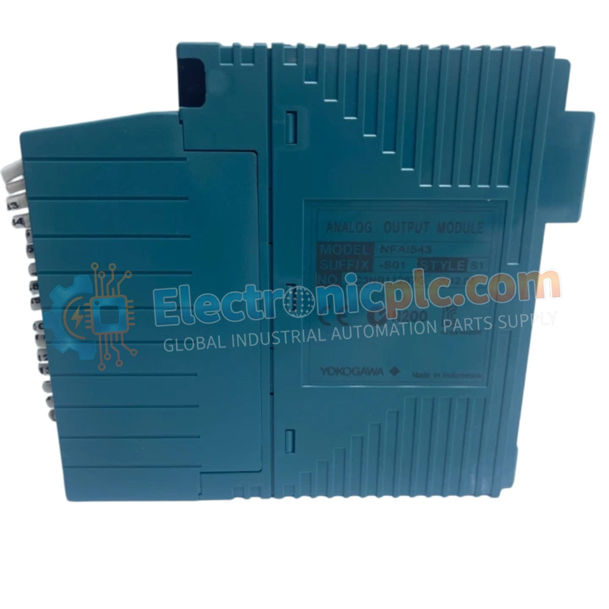
The YOKOGAWA NFAI543-500/A4500, also cataloged as the NFAI543 Analog Output Module, operates as a dedicated hardware component for high-precision current signal generation within STARDOM FCN and FCJ autonomous controller platforms.
The NFAI543-500/A4500 utilizes a specific suffix configuration to define operational standards. The -500 designator corresponds to the standard hardware version for high-density current loops, while the /A4500 suffix indicates the specific calibration and interface firmware version optimized for 16-channel analog control output.
| Parameter | Specification |
|---|---|
| Model | NFAI543-500/A4500 |
| Brand | YOKOGAWA |
| Origin | Japan |
| Weight | 0.4 kg |
| Dimensions | 25 mm x 203 mm x 152 mm |
| Operating Temp | 0 deg C to 55 deg C |
| Power Consumption | 5 VDC (backplane, 450 mA) + 24 VDC (loop) |
| Channel Density | 16 channels |
| Output Signal Range | 4-20 mA DC |
| Load Resistance | 0-750 Ohm |
| Conversion Resolution | 16-bit |
| Data Refresh Rate | 10 ms |
| Accuracy | +/- 0.3 % of full scale |
The NFAI543-500/A4500 architecture incorporates robust galvanic isolation to decouple the controller backplane from the field-side electrical environment. This design is required to suppress common-mode noise and prevent ground potential differences from affecting the 4-20 mA control signals. By utilizing 16-bit resolution, the module ensures precise positioning for valve actuators and accurate speed control for VFDs, while maintaining internal isolation barriers to preserve the integrity of the STARDOM controller logic.
Q: Can the NFAI543-500/A4500 support a load resistance greater than 750 Ohm?
A: No. The output drive capability is limited to 750 Ohm at 20 mA. Exceeding this resistance will cause the module to reach its voltage compliance limit, resulting in signal clipping and a loss of control accuracy.
Q: Is this module compatible with hot-swapping procedures?
A: Yes, provided the system configuration supports it. However, caution must be exercised to ensure that the process remains in a safe state during the removal or insertion of the module to avoid unintended output signals to field devices.


