
سلة التسوق الخاصة بي
0 عنصرًا
قطع غيار أصلية للأتمتة | توصيل سريع عالمي | ضمان لمدة 12 شهرًا — [احصل على عرض سعر]

تعمل الوحدة YOKOGAWA NFBU050-S10، والمصنفة أيضًا باسم وحدة القاعدة القصيرة NFBU050، كمكون أجهزة مخصص لتركيب شبكة التحكم الميدانية ضمن منصات نظام FCN-RTU. توفر هذه الوحدة الواجهة الميكانيكية والكهربائية للوحة الخلفية اللازمة لاستضافة...
التوافر: في الأوراق المالية
توصيل موثوق به في جميع أنحاء العالم
ضمان استرداد الأموال خلال 30 يومًا
هل تحتاج إلى مزيد من التفاصيل؟ اقرأ سياسة الشحن وسياسة الاسترداد الكاملة.


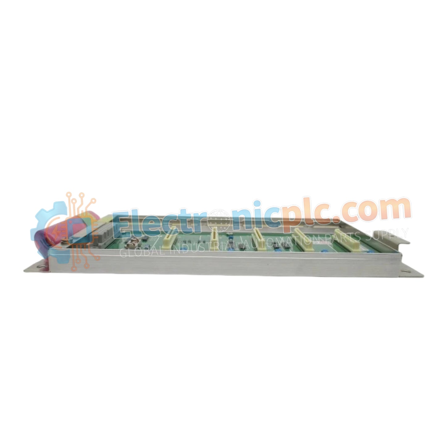
تعمل الوحدة YOKOGAWA NFBU050-S10، والمصنفة أيضًا باسم وحدة القاعدة القصيرة NFBU050، كمكون أجهزة مخصص لتركيب شبكة التحكم الميدانية ضمن منصات نظام FCN-RTU. توفر هذه الوحدة الواجهة الميكانيكية والكهربائية للوحة الخلفية اللازمة لاستضافة وحدات الإدخال/الإخراج في خزائن التحكم الصناعية محدودة المساحة.
يشير NFBU050-S10 إلى تهيئة وحدة أساسية محددة محسّنة لمعماريات Yokogawa FCN-RTU. تشير اللاحقة "S10" إلى تصميم القاعدة القياسي ذي الشكل القصير، والذي يستوعب عددًا محدودًا من فتحات الوحدات مقارنة باللوحات الأساسية كاملة الطول، مما يسهل التركيب عالي الكثافة في الرفوف القياسية مقاس 19 بوصة أو الحاويات المحلية.
| المعلمة | المواصفات |
| النموذج | NFBU050-S10 |
| العلامة التجارية | YOKOGAWA |
| المنشأ | اليابان |
| الوزن | 1.5 كجم |
| الأبعاد | 130 مم × 142.5 مم × 65.8 مم |
| درجة حرارة التشغيل | -20 درجة مئوية إلى 70 درجة مئوية |
| استهلاك الطاقة | 20 واط كحد أقصى |
| الارتفاع | حتى 3000 متر |
| التركيب | قضيب DIN أو رف 19 بوصة |
يستخدم NFBU050-S10 بروتوكولات ناقل اللوحة الخلفية الداخلية لدعم اتصال الوحدات داخل بنية FCN-RTU. يسهل توزيع الإشارة السلس للوحدات التي تدعم توصيل بروتوكول حلقة HART 4-20 مللي أمبير، مما يضمن نقل البيانات الميدانية بزمن انتقال منخفض إلى وحدة المعالجة المركزية. يفرض التصميم الميكانيكي عزل قناة إلى قناة من خلال تصميم اللوحة الاستراتيجي، مما يمنع التداخل الإشاري أثناء دورات الحصول على البيانات عالية السرعة.
س: هل هذه الوحدة الأساسية متوافقة مع عمليات التبديل السريع لوحدات الإدخال/الإخراج المتصلة؟
ج: يدعم NFBU050-S10 إزالة وإدخال وحدات الإدخال/الإخراج المتوافقة أثناء التشغيل، بشرط أن تسمح تهيئة نظام FCN-RTU بالتبديل السريع في الحالة الحالية. تأكد من أن جميع آليات الإغلاق مثبتة بالكامل للحفاظ على سلامة اتصال اللوحة الخلفية.
س: هل يمكن تركيب الوحدة الأساسية مباشرة في مناطق الاهتزاز العالي؟
ج: نعم، الوحدة مصممة للتركيب على قضبان DIN القياسية أو رفوف 19 بوصة. لبيئات الاهتزاز العالي، تحقق من أن مشابك قضبان DIN مغلقة وأن القاعدة مثبتة بإحكام باللوحة الخلفية للحاوية في جميع نقاط التركيب المحددة للتخفيف من التعب الميكانيكي.
تحقق من أن سطح التركيب مستوٍ وخالٍ من الحطام. إذا كنت تقوم بالتركيب على سكة DIN، فتأكد من تثبيت السكة بإحكام بهيكل الخزانة لتوفير مرجع أرضي مناسب.
قم بمحاذاة الوحدة الأساسية مع سكة التركيب واضغط بقوة حتى يستقر آلية القفل في مكانها.
عند تركيب الوحدات في القاعدة، تأكد من المحاذاة مع موصلات اللوحة الخلفية. اضغط بالتساوي على لوحة وجه الوحدة حتى تتساوى مع القاعدة.
أحكم ربط جميع مسامير التثبيت على لوحات وجه الوحدة لضمان أقصى قدر من الاستقرار الميكانيكي والتأريض الكهربائي لهيكل القاعدة.
تأكد من أن مصدر الطاقة للوحدة الأساسية ضمن النطاق المحدد قبل تشغيل النظام. تحقق من مستويات جهد الناقل الصحيحة عبر أطراف اللوحة الخلفية.


