انتقل إلى معلومات المنتج
1 ل 3

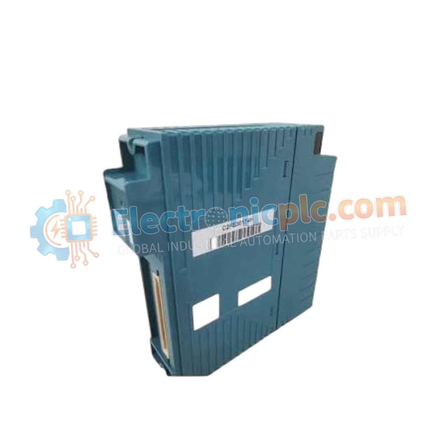
NFDV151-P60/B5S00 Digital Input Module YOKOGAWA

NFDV151-P60/B5S00 Digital Input Module YOKOGAWA

Configured for high-density signal acquisition in CENTUM control networks, the YOKOGAWA NFDV151-P60/B5S00 (NFDV151 Digital Input Module) provides direct physical signal processing for 32 discrete input channels.

Hardware Specifications

...
24 يشاهد الناس هذا الآن

التوافرفي الأوراق المالية

رمز المنتج: NFDV151-P60/B5S00
بائع: Yokogawa
Related Series:

الشحن والإرجاع

توصيل موثوق به في جميع أنحاء العالم

  • شركات الشحن: يتم الشحن عبر DHL أو FedEx أو UPS أو USPS .
  • الشحن: تتم معالجة الطلبات خلال يوم عمل واحد إلى يومين، ويتم شحنها خلال 3 إلى 5 أيام عمل .
  • التتبع: يتم توفير تفاصيل التتبع الكاملة عبر البريد الإلكتروني عند الشحن.

ضمان استرداد الأموال خلال 30 يومًا

  • الضمان: فترة إرجاع لمدة 30 يومًا للمنتجات المتوفرة في المخزون والمغلفة من المصنع.
  • الشروط: يجب أن تكون المنتجات غير مفتوحة وغير مستخدمة وفي عبوتها الأصلية.
  • الأصالة: نضمن أن تكون الأجهزة أصلية 100% .

هل تحتاج إلى مزيد من التفاصيل؟ اقرأ سياسة الشحن وسياسة الاسترداد الكاملة.

الأصالة والضمان

  • ضمان أصلي: نحن نوفر فقط قطع غيار أصلية 100%، جديدة تمامًا، ومغلقة من المصنع .
  • تغطية كاملة: كل مكون مدعوم بضمان شامل لمدة 12 شهرًا من تاريخ الشراء.
  • إمكانية التتبع: جميع المنتجات تأتي مع وثائق المصنع الأصلية والملحقات اللازمة للامتثال الكامل للمعايير الصناعية.

الدعم الفني والتوريد

  • مساعدة الخبراء: يقدم فريقنا الفني استشارات مجانية لمساعدتك في التحقق من التوافق مع أنظمة DCS و PLC.
  • مصادر القطع النادرة: متخصصون في المكونات القديمة والتي يصعب العثور عليها من Allen-Bradley و Siemens و ABB و HIMA وغيرها.
  • للاستفسارات المتعلقة بالكميات الكبيرة: تواصلوا معنا على pambo@5gplc.com للحصول على أسعار الكميات الكبيرة أو عروض أسعار المشاريع المخصصة.
عرض تفاصيل المنتج الكاملة

Configured for high-density signal acquisition in CENTUM control networks, the YOKOGAWA NFDV151-P60/B5S00 (NFDV151 Digital Input Module) provides direct physical signal processing for 32 discrete input channels.

Hardware Specifications

Parameter Specification
Model NFDV151-P60/B5S00
Brand YOKOGAWA
Origin Japan
Weight 0.3 kg
Dimensions Standard NFDV Series form factor
Operating Temp Not specified (Standard industrial range)
Power Consumption 500 mA (5 V DC)
Input Channels 32
Rated Voltage 24 V DC
Input ON Voltage 18 to 26.4 V DC
Input OFF Voltage 5.0 V DC or less
Withstanding Voltage 2000 V AC (Input-System)

Channel-to-Channel Isolation and Input Logic

The NFDV151-P60/B5S00 utilizes integrated opto-isolation to maintain signal integrity across all 32 channels. This architecture ensures galvanic isolation between the field input circuits and the internal system bus, preventing cross-channel interference and protecting system components from transient voltage surges. The module supports a rated input voltage of 24 V DC with a defined switching threshold to ensure stable detection of binary states in industrial environments.

Frequently Asked Questions

Q: Is this module capable of hot-swapping during active system operation?

A: Hot-swapping the NFDV151 module is permissible only when the associated field power is isolated and the system software is configured for non-interruptive module replacement. Ensure the rack backplane is powered before module insertion to avoid initialization errors.

Q: How should the common lines be managed to maintain the 500 V AC isolation rating?

A: Proper segregation of common return paths is required to maintain the 500 V AC isolation between channel groups. Shielded cabling should be used for all inputs, with the shield connected to the chassis ground at the cabinet entry point to suppress induced electromagnetic noise.

Field Installation Guidelines

  1. Verify that the field wiring voltage does not exceed the maximum rating of 30.0 V DC to prevent internal component damage.
  2. Ensure the module is firmly seated into the designated backplane slot and that the locking mechanism is fully engaged to ensure ground continuity.
  3. Terminate all 32 input channels using shielded twisted-pair cabling, ensuring proper color coding matches the I/O mapping configuration.
  4. Verify the input status logic via the system diagnostic interface to confirm that signals transition correctly between OFF and ON states.
  5. Keep signal cabling isolated from high-voltage AC power lines by a minimum distance of 300 mm to minimize EMI coupling.