سلة التسوق الخاصة بي
0 عنصرًا
قطع غيار أصلية للأتمتة | توصيل سريع عالمي | ضمان لمدة 12 شهرًا — [احصل على عرض سعر]

The YOKOGAWA NFPW444-10 S2, also cataloged as the NFPW444-10 Power Supply Module, operates as a dedicated hardware component for power regulation and distribution within Yokogawa DCS control platforms. This module...
التوافر: الكمية المتبقية: 99
توصيل موثوق به في جميع أنحاء العالم
ضمان استرداد الأموال خلال 30 يومًا
هل تحتاج إلى مزيد من التفاصيل؟ اقرأ سياسة الشحن وسياسة الاسترداد الكاملة.

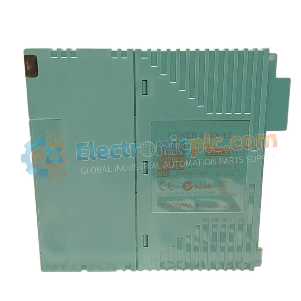
The YOKOGAWA NFPW444-10 S2, also cataloged as the NFPW444-10 Power Supply Module, operates as a dedicated hardware component for power regulation and distribution within Yokogawa DCS control platforms. This module executes the conversion of incoming supply voltage into regulated DC output, maintaining the operational voltage rails required for system backplane logic and associated instrumentation.
The model identifier NFPW444-10 S2 designates a specific hardware iteration. The "S2" suffix indicates an optimized revision for system backplanes, ensuring mechanical alignment and interface compatibility with standard Yokogawa control bus architectures.
| Parameter | Specification |
|---|---|
| Model | NFPW444-10 S2 |
| Brand | Yokogawa |
| Origin | Japan |
| Weight | 1.4 kg |
| Dimensions | 5.5 cm x 15.0 cm x 11.2 cm |
| Operating Temp | 0 deg C to 50 deg C |
| Power Consumption | Load dependent |
The NFPW444-10 S2 ensures consistent voltage delivery, which is necessary to maintain the integrity of the 4-20 mA HART loop protocol across the control environment. The unit features channel-to-channel isolation to prevent the propagation of common-mode electrical noise or ground loops between control segments. Additionally, the internal thermal management system facilitates cold junction compensation (CJC), providing the electrical stability required for high-precision process measurement and control tasks.
Q: Does the NFPW444-10 S2 support redundant power supply configurations?
A: Yes, this module supports parallel operation within a redundant power supply chassis. The internal bus circuitry is designed to manage automatic load balancing and failover, provided that both modules are connected to independent power input lines.
Q: How can I verify that the module is operating within nominal parameters?
A: Monitor the status LEDs on the front panel and verify the DC output voltage at the backplane test points using a calibrated multimeter. Any deviation from the nominal output voltage under load may indicate internal component degradation.

