انتقل إلى معلومات المنتج
1 ل 3

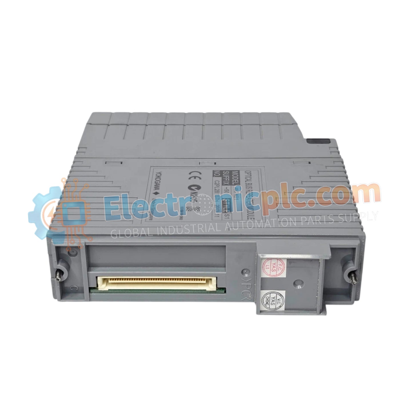
Optical ESB Bus Repeater Module Yokogawa ANT401-50

Optical ESB Bus Repeater Module Yokogawa ANT401-50

Configured for extended transmission distance in CENTUM control networks, the Yokogawa ANT401-50 (ANT401-50 Optical ESB Bus Repeater Module) provides direct physical/electrical execution of ESB signal conversion between electrical and optical...

25 يشاهد الناس هذا الآن

التوافرفي الأوراق المالية

رمز المنتج: ANT401-50
بائع: Yokogawa

الشحن والإرجاع

توصيل موثوق به في جميع أنحاء العالم

  • شركات الشحن: يتم الشحن عبر DHL أو FedEx أو UPS أو USPS .
  • الشحن: تتم معالجة الطلبات خلال يوم عمل واحد إلى يومين، ويتم شحنها خلال 3 إلى 5 أيام عمل .
  • التتبع: يتم توفير تفاصيل التتبع الكاملة عبر البريد الإلكتروني عند الشحن.

ضمان استرداد الأموال خلال 30 يومًا

  • الضمان: فترة إرجاع لمدة 30 يومًا للمنتجات المتوفرة في المخزون والمغلفة من المصنع.
  • الشروط: يجب أن تكون المنتجات غير مفتوحة وغير مستخدمة وفي عبوتها الأصلية.
  • الأصالة: نضمن أن تكون الأجهزة أصلية 100% .

هل تحتاج إلى مزيد من التفاصيل؟ اقرأ سياسة الشحن وسياسة الاسترداد الكاملة.

الأصالة والضمان

  • ضمان أصلي: نحن نوفر فقط قطع غيار أصلية 100%، جديدة تمامًا، ومغلقة من المصنع .
  • تغطية كاملة: كل مكون مدعوم بضمان شامل لمدة 12 شهرًا من تاريخ الشراء.
  • إمكانية التتبع: جميع المنتجات تأتي مع وثائق المصنع الأصلية والملحقات اللازمة للامتثال الكامل للمعايير الصناعية.

الدعم الفني والتوريد

  • مساعدة الخبراء: يقدم فريقنا الفني استشارات مجانية لمساعدتك في التحقق من التوافق مع أنظمة DCS و PLC.
  • مصادر القطع النادرة: متخصصون في المكونات القديمة والتي يصعب العثور عليها من Allen-Bradley و Siemens و ABB و HIMA وغيرها.
  • للاستفسارات المتعلقة بالكميات الكبيرة: تواصلوا معنا على pambo@5gplc.com للحصول على أسعار الكميات الكبيرة أو عروض أسعار المشاريع المخصصة.
عرض تفاصيل المنتج الكاملة

Configured for extended transmission distance in CENTUM control networks, the Yokogawa ANT401-50 (ANT401-50 Optical ESB Bus Repeater Module) provides direct physical/electrical execution of ESB signal conversion between electrical and optical domains.

Hardware Specifications

Parameter Specification
Model ANT401-50
Brand Yokogawa
Origin Japan
Weight 0.5 kg
Dimensions 200 mm x 50 mm x 30 mm
Operating Temp -20 deg C to 60 deg C
Power Consumption Not Specified
Transmission Distance Up to 5 km
Communication Interface Optical ESB bus
Input Voltage 24 VDC

Channel-to-Channel Isolation and Data Integrity

The ANT401-50 facilitates signal conversion to overcome the distance limitations inherent in copper-based ESB bus segments. The module architecture ensures channel-to-channel isolation, preventing electrical ground loops between disparate control nodes connected via optical fiber. By converting electrical ESB signals to optical pulses, the module effectively eliminates electromagnetic interference (EMI) impacts on data transmission across the 5 km range. This conversion process is transparent to the controller, maintaining deterministic communication timing required for real-time DCS operations.

Frequently Asked Questions

Q: Does the ANT401-50 module require specific fiber optic cable types for optimal performance?

A: Yes. The module is engineered for compatibility with standard multimode or single-mode fiber optic cables, depending on the specific link budget and distance requirements of the installation. Ensure cable ends are terminated and polished to minimize signal attenuation.

Q: Is this module capable of supporting hot-swapping during active operation?

A: No. The ANT401-50 does not support hot-swapping. The power supply must be disconnected and the ESB bus communication halted prior to the physical installation or removal of the module from the mounting backplane.

Field Installation Guidelines

  1. Ensure the module is mounted in a well-ventilated enclosure to maintain ambient temperatures within the -20 deg C to 60 deg C range.
  2. Verify that the 24 VDC power source is stable and correctly polarized before connecting the power terminals to the module.
  3. Clean all optical connectors with industry-standard fiber cleaning tools before inserting them into the module ports to prevent signal loss caused by contamination.
  4. Route optical cables through dedicated conduit, keeping them separated from high-voltage power cables to comply with standard industrial cabling practices.
  5. Secure the module firmly to the DIN-rail or chassis mounting plate to prevent vibration-induced intermittent connections, ensuring all grounding lugs are properly fastened.