سلة التسوق الخاصة بي
0 عنصرًا
قطع غيار أصلية للأتمتة | توصيل سريع عالمي | ضمان لمدة 12 شهرًا — [احصل على عرض سعر]

Configured for power distribution and bus management within industrial control architectures, the Yokogawa S9756UV (S9756UV Power Supply Bus Unit) provides direct electrical regulation and signal continuity for modular system racks.
...التوافر: في الأوراق المالية
توصيل موثوق به في جميع أنحاء العالم
ضمان استرداد الأموال خلال 30 يومًا
هل تحتاج إلى مزيد من التفاصيل؟ اقرأ سياسة الشحن وسياسة الاسترداد الكاملة.
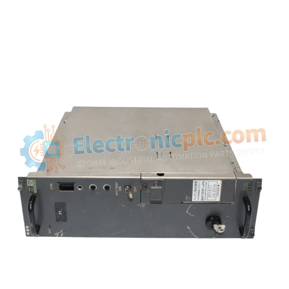

Configured for power distribution and bus management within industrial control architectures, the Yokogawa S9756UV (S9756UV Power Supply Bus Unit) provides direct electrical regulation and signal continuity for modular system racks.
| Parameter | Specification |
|---|---|
| Model | S9756UV |
| Brand | Yokogawa |
| Origin | japan |
| Weight | 1.6 kg |
| Dimensions | 23 cm x 12 cm x 5.2 cm |
| Operating Temp | Standard industrial range |
| Power Type | Bus power supply management |
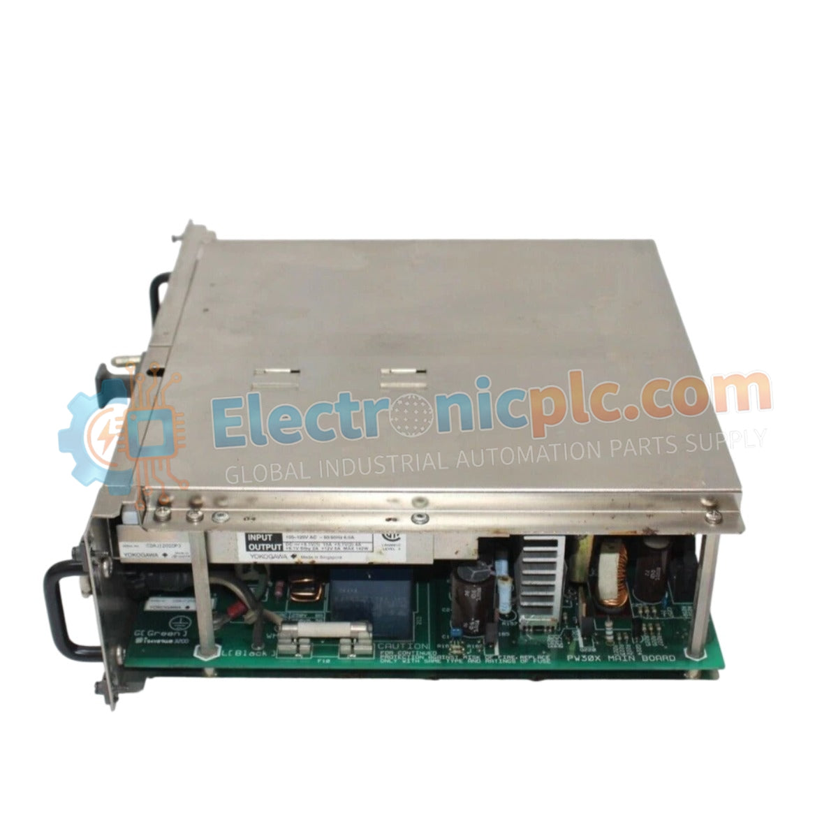
The S9756UV architecture is engineered to provide stable voltage regulation and power distribution to sensitive electronic modules within Yokogawa control systems. By serving as the central power interface for the bus rack, the unit ensures that input power is properly conditioned before reaching CPU, I/O, and communication modules, mitigating the risk of voltage fluctuations or noise ingress from the primary power source. The unit's robust construction facilitates long-term durability in high-density rack configurations, providing the necessary current capacity to support the full operational load of the associated backplane and its mounted hardware.
Q: Does the S9756UV require redundant power input configuration?
A: Depending on the specific system design, the S9756UV is typically integrated into the primary power distribution network. Ensure that input wiring is performed according to the specific rack configuration guidelines to maintain the system's intended redundancy level.
Q: How can I verify the status of the power supply bus unit during routine maintenance?
A: Status indication is typically provided via diagnostic LEDs located on the front face of the module. Consult the system's technical manual to interpret the status indicators and ensure the module is delivering the correct output voltage to the backplane.


