سلة التسوق الخاصة بي
0 عنصرًا
قطع غيار أصلية للأتمتة | توصيل سريع عالمي | ضمان لمدة 12 شهرًا — [احصل على عرض سعر]

The YOKOGAWA PW402, also cataloged as the PW402 Power Supply Module, operates as a dedicated hardware component for power regulation within DCS process control platforms.
التوافر: الكمية المتبقية: 99
توصيل موثوق به في جميع أنحاء العالم
ضمان استرداد الأموال خلال 30 يومًا
هل تحتاج إلى مزيد من التفاصيل؟ اقرأ سياسة الشحن وسياسة الاسترداد الكاملة.

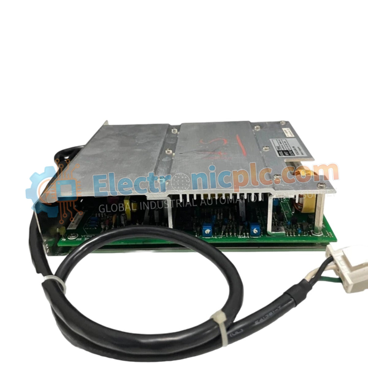
The YOKOGAWA PW402, also cataloged as the PW402 Power Supply Module, operates as a dedicated hardware component for power regulation within DCS process control platforms.
| Parameter | Specification |
| Model | PW402 |
| Brand | YOKOGAWA |
| Origin | Subject to factory batch |
| Weight | 2 kg |
| Dimensions | 5.1 cm x 22.9 cm x 20.3 cm |
| Operating Temp | Standard industrial ambient range |
| Power Consumption | Load dependent |
| Input Voltage | 100-120 VAC or 220-240 VAC |
| Output Voltage | +12 VDC and +24 VDC (Base model) |
The module integrates specialized circuitry for channel-to-channel isolation and voltage regulation required in DCS instrumentation loops. To maintain the requisite output stability, the power supply utilizes internal feedback loops to compensate for variations in line voltage. The +12 VDC and +24 VDC rails are engineered for low ripple characteristics, facilitating stable operation for sensitive analog input and output modules within the YOKOGAWA ecosystem. Proper thermal management is required, as the unit dissipates heat during high-load operations, necessitating adequate cabinet ventilation to prevent internal component fatigue.
Q: What are the primary considerations for the input voltage configuration?
A: The input stage is designed for dual-range operation. Users must verify the specific model variation requirements (100-120 VAC or 220-240 VAC) prior to commissioning to ensure the internal transformer taps are correctly matched to the field supply.
Q: How should the multi-output rails be managed under load?
A: The PW402 provides separate output rails for +12 VDC and +24 VDC. Load distribution should be balanced to prevent current saturation on either rail. Consult the system power budget documentation to confirm that total wattage consumption does not exceed the power supply design limits.

