سلة التسوق الخاصة بي
0 عنصرًا
قطع غيار أصلية للأتمتة | توصيل سريع عالمي | ضمان لمدة 12 شهرًا — [احصل على عرض سعر]

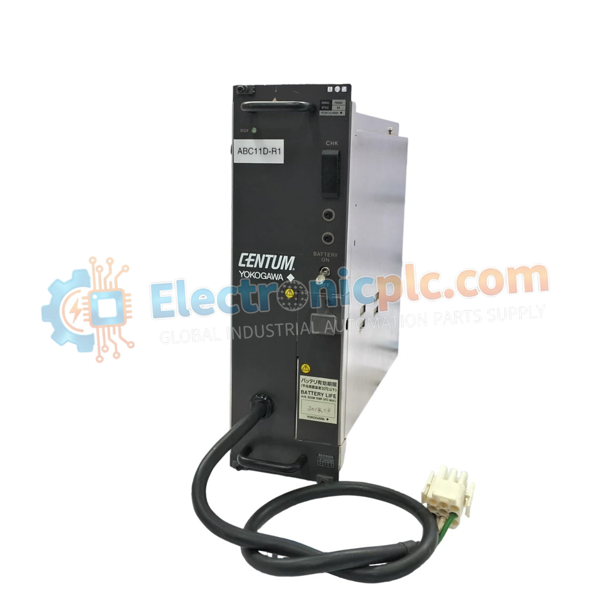
يعمل YOKOGAWA PW301/100، والمصنف أيضًا كوحدة الطاقة PW301، كأحد مكونات الأجهزة المخصصة لتنظيم الطاقة ضمن منصات التحكم في عمليات أنظمة التحكم الموزعة (DCS).
التوافر: الكمية المتبقية: 99
توصيل موثوق به في جميع أنحاء العالم
ضمان استرداد الأموال خلال 30 يومًا
هل تحتاج إلى مزيد من التفاصيل؟ اقرأ سياسة الشحن وسياسة الاسترداد الكاملة.


يعمل YOKOGAWA PW301/100، والمصنف أيضًا كوحدة الطاقة PW301، كأحد مكونات الأجهزة المخصصة لتنظيم الطاقة ضمن منصات التحكم في عمليات أنظمة التحكم الموزعة (DCS).
| المعلمة | المواصفة |
| النموذج | PW301/100 |
| العلامة التجارية | YOKOGAWA |
| المنشأ | حسب دفعة المصنع |
| الوزن | 3.3 كجم |
| الأبعاد | 27.9 سم × 10.2 سم × 27.9 سم |
| درجة حرارة التشغيل | النطاق المحيطي الصناعي القياسي |
| استهلاك الطاقة | يعتمد على الحمل |
| تيار الإدخال | 6 أمبير |
| جهد الإدخال | 100-120 فولت تيار متردد |
| تيار الإخراج | 15 أمبير |
| جهد الإخراج | 5.1 فولت تيار مستمر |
تتضمن الوحدة دوائر متخصصة للعزل من قناة إلى قناة وتنظيم الجهد المطلوب لمكونات نظام CENTUM VP DCS. للحفاظ على أداء خرج ثابت، تستخدم وحدة تزويد الطاقة آليات تغذية راجعة داخلية للتعويض عن تقلبات خط الإدخال ضمن نطاق 100-120 فولت تيار متردد. تم تصميم بنية خرج 5.1 فولت تيار مستمر لتقليل خصائص التموج، مما يسهل التشغيل المستقر لدوائر المستوى المنطقي ووحدات الاتصال. يلزم إدارة حرارية فعالة، مما يستدعي تدفق هواء كافٍ للخزانة لمنع تدهور أداء المكونات أثناء التشغيل المستمر في تكوينات الرف عالية الكثافة.
س: ما هي الاعتبارات الأساسية عند دمج وحدة تزويد الطاقة هذه في رف CENTUM VP؟
ج: تأكد من أن الوحدة مثبتة بالكامل في موصل اللوحة الخلفية لضمان التلامس الكهربائي الصحيح لتوزيع الطاقة. يجب قفل مزاليج التثبيت الميكانيكية للحفاظ على الاستقرار الهيكلي واستمرارية تأريض الهيكل.
س: هل هذه الوحدة قادرة على دعم جهود إدخال أعلى؟
ج: تم تصنيف PW301/100 خصيصًا لإدخال 100-120 فولت تيار متردد. سيؤدي تشغيل هذه الوحدة عند 220-240 فولت تيار متردد بدون محول خفض مناسب إلى تلف مرحلة الإدخال الداخلية ومكونات المنظم الأساسي.


