انتقل إلى معلومات المنتج
1 ل 3

PW301 S4 YOKOGAWA Power Module Datasheet & Technical Manual

PW301 S4 YOKOGAWA Power Module Datasheet & Technical Manual

he YOKOGAWA PW301 S4, also cataloged as the PW301 Power Module, operates as a dedicated hardware component for power regulation within Yokogawa DCS platforms. This module executes the conversion of...

26 يشاهد الناس هذا الآن

التوافرالكمية المتبقية: 99

رمز المنتج: PW301 S4
بائع: Yokogawa
Related Series:

الشحن والإرجاع

توصيل موثوق به في جميع أنحاء العالم

  • شركات الشحن: يتم الشحن عبر DHL أو FedEx أو UPS أو USPS .
  • الشحن: تتم معالجة الطلبات خلال يوم عمل واحد إلى يومين، ويتم شحنها خلال 3 إلى 5 أيام عمل .
  • التتبع: يتم توفير تفاصيل التتبع الكاملة عبر البريد الإلكتروني عند الشحن.

ضمان استرداد الأموال خلال 30 يومًا

  • الضمان: فترة إرجاع لمدة 30 يومًا للمنتجات المتوفرة في المخزون والمغلفة من المصنع.
  • الشروط: يجب أن تكون المنتجات غير مفتوحة وغير مستخدمة وفي عبوتها الأصلية.
  • الأصالة: نضمن أن تكون الأجهزة أصلية 100% .

هل تحتاج إلى مزيد من التفاصيل؟ اقرأ سياسة الشحن وسياسة الاسترداد الكاملة.
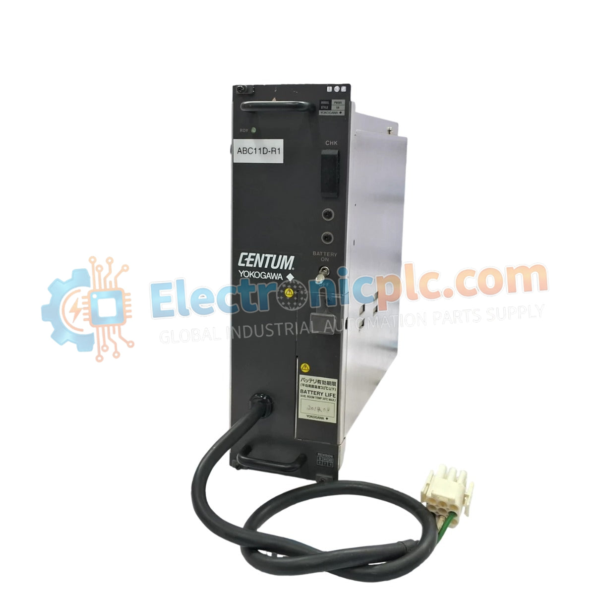
الأصالة والضمان

  • ضمان أصلي: نحن نوفر فقط قطع غيار أصلية 100%، جديدة تمامًا، ومغلقة من المصنع .
  • تغطية كاملة: كل مكون مدعوم بضمان شامل لمدة 12 شهرًا من تاريخ الشراء.
  • إمكانية التتبع: جميع المنتجات تأتي مع وثائق المصنع الأصلية والملحقات اللازمة للامتثال الكامل للمعايير الصناعية.

الدعم الفني والتوريد

  • مساعدة الخبراء: يقدم فريقنا الفني استشارات مجانية لمساعدتك في التحقق من التوافق مع أنظمة DCS و PLC.
  • مصادر القطع النادرة: متخصصون في المكونات القديمة والتي يصعب العثور عليها من Allen-Bradley و Siemens و ABB و HIMA وغيرها.
  • للاستفسارات المتعلقة بالكميات الكبيرة: تواصلوا معنا على pambo@5gplc.com للحصول على أسعار الكميات الكبيرة أو عروض أسعار المشاريع المخصصة.
عرض تفاصيل المنتج الكاملة

he YOKOGAWA PW301 S4, also cataloged as the PW301 Power Module, operates as a dedicated hardware component for power regulation within Yokogawa DCS platforms. This module executes the conversion of incoming supply voltage into a regulated DC output, maintaining the operational voltage rails required for system backplane logic and associated instrumentation.

Suffix Breakdown & Model Matrix

The model identifier PW301 S4 designates a specific hardware iteration. The "S4" suffix indicates an optimized revision for high-density chassis backplanes, ensuring mechanical alignment and interface compatibility with standard Yokogawa control bus architectures.

Hardware Specifications

Parameter Specification
Model PW301 S4
Brand Yokogawa
Origin USA
Weight 3.3 kg
Dimensions 10.2 cm x 27.9 cm x 27.9 cm
Operating Temp 0 deg C to 50 deg C
Power Consumption Load dependent

Process Control and Signal Isolation

The PW301 S4 ensures consistent voltage delivery, which is necessary to maintain the integrity of the 4-20 mA HART loop protocol across the control environment. The unit features channel-to-channel isolation to prevent the propagation of common-mode electrical noise or ground loops between control segments. Additionally, the internal thermal management system facilitates cold junction compensation (CJC), providing the electrical stability required for high-precision process measurement and control tasks.

Frequently Asked Questions

Q: Does the PW301 S4 support redundant power supply configurations?

A: Yes, this module supports parallel operation within a redundant power supply chassis. The internal bus circuitry is designed to manage automatic load balancing and failover, provided that both modules are connected to independent power input lines.

Q: How can I verify that the module is operating within nominal parameters?

A: Monitor the status LEDs on the front panel and verify the DC output voltage at the backplane test points using a calibrated multimeter. Any deviation from the nominal output voltage under load may indicate internal component degradation.

Field Installation Guidelines

  1. Confirm that the input power source is de-energized before mounting the module to the backplane.
  2. Align the module with the chassis guide rails and apply firm pressure until the connector pins fully engage with the backplane bus.
  3. Tighten the front panel fastening hardware to ensure a low-impedance connection to the chassis protective earth (PE) ground.
  4. Verify the output voltage at the backplane test points using a calibrated multimeter before commissioning the connected I/O cards.
  5. Inspect the wiring connections periodically to ensure terminals remain tight, as vibration in industrial environments can lead to intermittent power delivery.