سلة التسوق الخاصة بي
0 عنصرًا
قطع غيار أصلية للأتمتة | توصيل سريع عالمي | ضمان لمدة 12 شهرًا — [احصل على عرض سعر]

Configured for power regulation and distribution in DCS platforms, the YOKOGAWA PW481-10 (PW481-10 Power Supply Module) provides direct physical/electrical execution. This module is engineered to convert incoming supply voltage into...
التوافر: الكمية المتبقية: 99
توصيل موثوق به في جميع أنحاء العالم
ضمان استرداد الأموال خلال 30 يومًا
هل تحتاج إلى مزيد من التفاصيل؟ اقرأ سياسة الشحن وسياسة الاسترداد الكاملة.


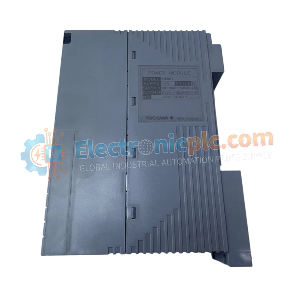
Configured for power regulation and distribution in DCS platforms, the YOKOGAWA PW481-10 (PW481-10 Power Supply Module) provides direct physical/electrical execution. This module is engineered to convert incoming supply voltage into regulated DC output, maintaining operational stability for connected control cards and field instrumentation within the Yokogawa DCS architecture.
| Parameter | Specification |
|---|---|
| Model | PW481-10 |
| Brand | Yokogawa |
| Origin | USA |
| Weight | 0.9 kg |
| Dimensions | 5.1 cm x 20.3 cm x 15.2 cm |
| Operating Temp | -10 deg C to 60 deg C |
| Power Consumption | Dependent on system load |
The PW481-10 facilitates stable voltage rails necessary for process control stability. The unit incorporates channel-to-channel isolation to prevent ground loops and electrical noise injection into the control bus. Consistent voltage delivery is maintained across varying load conditions to ensure the integrity of the 4-20 mA HART loop protocol utilized by downstream instrumentation. Cold junction compensation (CJC) and precise thermal management are implemented within the power stage to maintain performance accuracy across the operational temperature range.
Q: Does the PW481-10 support field hot-swapping during active system operation?
A: Hot-swapping depends on the specific backplane and DCS chassis configuration. Consult the system integration manual to verify if the rack backplane supports power module extraction without triggering a processor reset.
Q: What are the primary indicators of a power failure on this module?
A: The module front panel typically features status LEDs. Verify that the output voltage is within nominal parameters using a calibrated multimeter across the output terminals if the status light indicates a fault.


