سلة التسوق الخاصة بي
0 عنصرًا
قطع غيار أصلية للأتمتة | توصيل سريع عالمي | ضمان لمدة 12 شهرًا — [احصل على عرض سعر]

The YOKOGAWA PW481-11, also cataloged as the PW481 Power Supply Module, operates as a dedicated hardware component for power distribution within Yokogawa FCU, FIO Node Unit, and Optical ESB Bus...
التوافر: الكمية المتبقية: 99
توصيل موثوق به في جميع أنحاء العالم
ضمان استرداد الأموال خلال 30 يومًا
هل تحتاج إلى مزيد من التفاصيل؟ اقرأ سياسة الشحن وسياسة الاسترداد الكاملة.


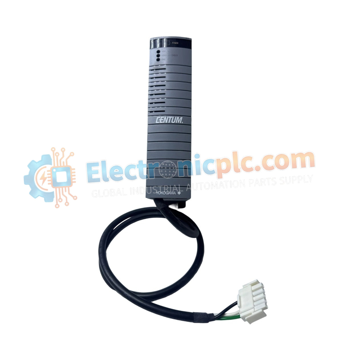
The YOKOGAWA PW481-11, also cataloged as the PW481 Power Supply Module, operates as a dedicated hardware component for power distribution within Yokogawa FCU, FIO Node Unit, and Optical ESB Bus Repeater Unit platforms. This module is exclusively engineered to provide system-specific voltage regulation for these control nodes and cannot be utilized as a generic power supply.
The model identifier PW481-11 indicates a specific hardware revision for the 100-120 VAC input series. The "-11" suffix corresponds to the standard hardware configuration for integration within the Yokogawa FIO and control platform backplanes.
| Parameter | Specification |
|---|---|
| Model | PW481-11 |
| Brand | Yokogawa |
| Origin | Japan |
| Weight | 1.0 kg |
| Input Voltage | 100–120 VAC (+/- 10%) |
| Input Frequency | 50/60 Hz (+/- 3 Hz) |
| Power Consumption | 200 VA (max) |
| Operating Temp | 0 deg C to 50 deg C |
The PW481-11 is designed to maintain precise voltage rails across the backplane of connected Yokogawa control units. The module integrates channel-to-channel isolation to suppress electromagnetic interference within the ESB bus architecture. Its design ensures operational continuity for the FCU and FIO Node units by mitigating line transients. Cold junction compensation (CJC) and thermal management are strictly aligned with the requirements of the host control hardware to maintain system-wide synchronization.
Q: Can the PW481-11 be used as a standalone power supply for third-party instruments?
A: No. The PW481-11 is an exclusive power module specifically tailored for Yokogawa FCU, FIO Node Units, and Optical ESB Bus Repeater Units. It lacks the standard voltage regulation and protection features required for generic industrial applications.
Q: How is the module grounded to the chassis?
A: The module front panel is designed to provide a low-impedance path to the chassis protective earth (PE) ground when the fastening screws are fully torqued. Ensure these screws are secure to prevent common-mode noise issues.


