سلة التسوق الخاصة بي
0 عنصرًا
قطع غيار أصلية للأتمتة | توصيل سريع عالمي | ضمان لمدة 12 شهرًا — [احصل على عرض سعر]

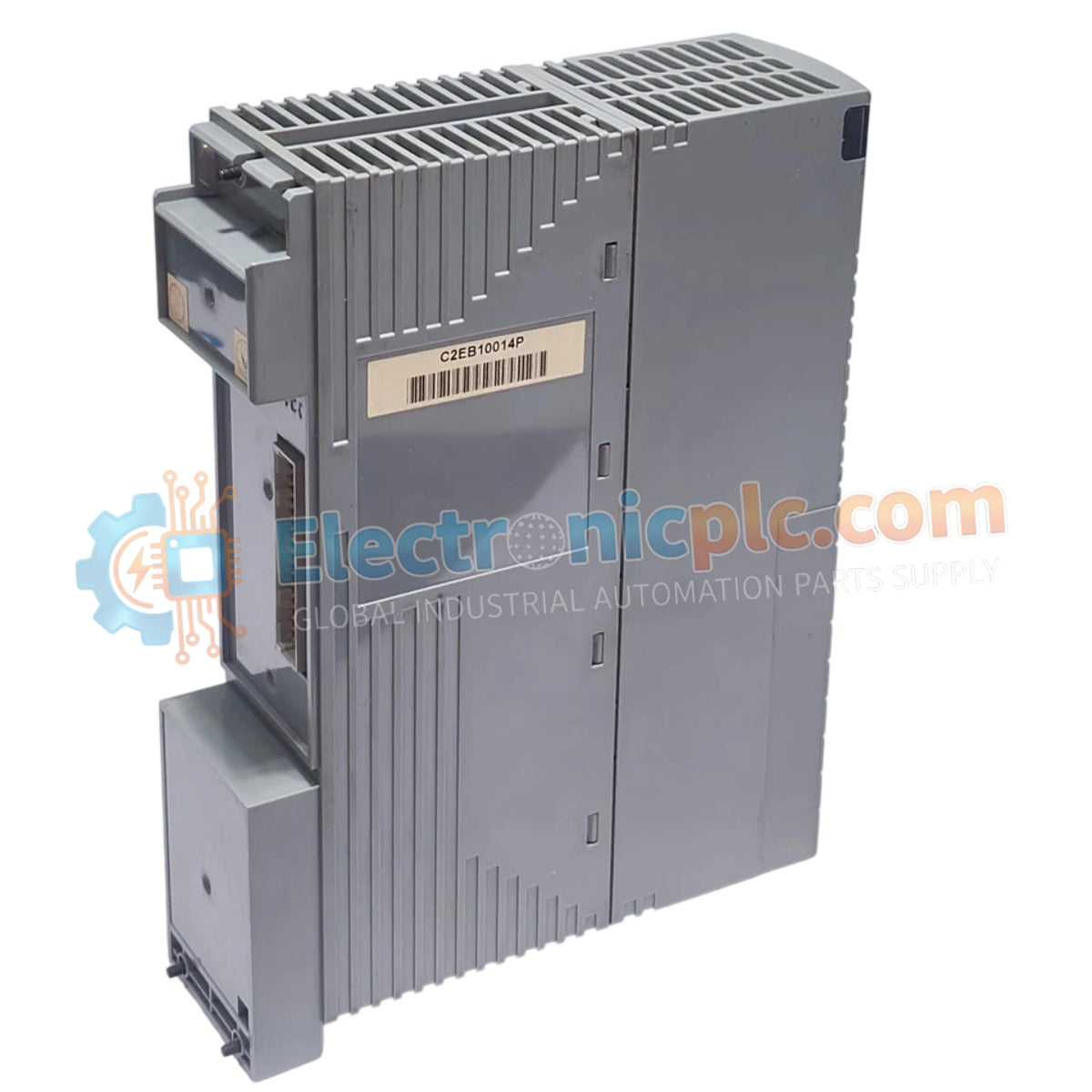
Configured for power conversion in DCS process control platforms, the YOKOGAWA PW482-10 (PW482-10 Power Supply Module) provides direct physical/electrical execution.
التوافر: الكمية المتبقية: 99
توصيل موثوق به في جميع أنحاء العالم
ضمان استرداد الأموال خلال 30 يومًا
هل تحتاج إلى مزيد من التفاصيل؟ اقرأ سياسة الشحن وسياسة الاسترداد الكاملة.


Configured for power conversion in DCS process control platforms, the YOKOGAWA PW482-10 (PW482-10 Power Supply Module) provides direct physical/electrical execution.
| Parameter | Specification |
| Model | PW482-10 |
| Brand | YOKOGAWA |
| Origin | Subject to factory batch |
| Weight | 0.9 kg |
| Dimensions | 5.1 cm x 20.3 cm x 15.2 cm |
| Operating Temp | -20 deg C to +70 deg C |
| Power Consumption | 480 W (Max output) |
| Input Voltage | 100-120 VAC / 220-240 VAC |
| Output Voltage | +12 VDC / +24 VDC |
| Output Current | 40 A at 12 VDC |
The module employs specialized circuitry for channel-to-channel isolation and voltage regulation required in DCS instrumentation loops. To maintain the requisite output stability, the power supply utilizes internal feedback loops to compensate for variations in line voltage. The +12 VDC and +24 VDC rails are designed for low ripple characteristics, facilitating stable operation for sensitive analog input and output modules within the YOKOGAWA architecture. Proper thermal management is required, as the unit operates across an extended range of -20 deg C to +70 deg C, necessitating adequate cabinet ventilation to prevent internal component fatigue.
Q: Can the PW482-10 be utilized in environments with high electromagnetic interference?
A: Yes, provided that proper shielded cabling and a low-impedance ground path are established to maintain the integrity of the output voltage rails against external transient interference.
Q: Is the +12 VDC and +24 VDC output combination fixed, or can it be adjusted?
A: The voltage rails are fixed output values determined by the internal regulator configuration. There are no user-adjustable potentiometers for output voltage modification on this module.


