سلة التسوق الخاصة بي
0 عنصرًا
قطع غيار أصلية للأتمتة | توصيل سريع عالمي | ضمان لمدة 12 شهرًا — [احصل على عرض سعر]

The YOKOGAWA PW482-51, also cataloged as the PW482-51 Power Supply Module, operates as a dedicated hardware component for power regulation and distribution within Yokogawa DCS platforms. This module executes the...
التوافر: الكمية المتبقية: 99
توصيل موثوق به في جميع أنحاء العالم
ضمان استرداد الأموال خلال 30 يومًا
هل تحتاج إلى مزيد من التفاصيل؟ اقرأ سياسة الشحن وسياسة الاسترداد الكاملة.


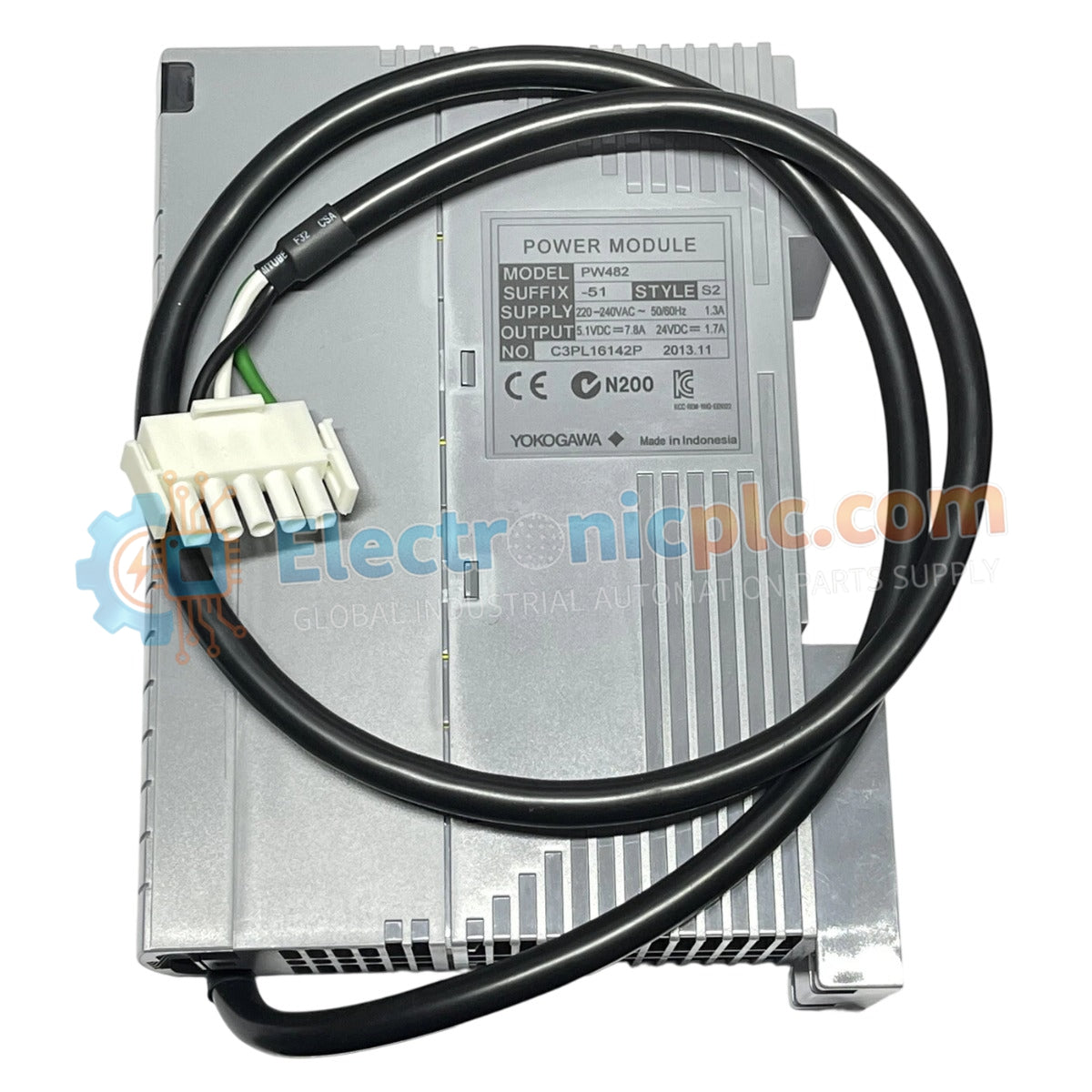
The YOKOGAWA PW482-51, also cataloged as the PW482-51 Power Supply Module, operates as a dedicated hardware component for power regulation and distribution within Yokogawa DCS platforms. This module executes the conversion of incoming supply voltage into regulated DC output, maintaining the operational stability required for backplane-mounted control cards and integrated field instrumentation.
The model identifier PW482-51 signifies a specific hardware configuration. The "51" suffix indicates a revision optimized for electrical compatibility and form-factor integration within standard Yokogawa DCS chassis backplanes.
| Parameter | Specification |
|---|---|
| Model | PW482-51 |
| Brand | Yokogawa |
| Origin | Japan |
| Weight | 0.9 kg |
| Dimensions | 5.1 cm x 20.3 cm x 15.2 cm |
| Operating Temp | 0 deg C to 50 deg C |
| Power Consumption | Load dependent |
The PW482-51 facilitates stable voltage rails necessary for process control continuity. The unit incorporates channel-to-channel isolation to prevent ground loops and electrical noise injection into the control bus. Consistent voltage delivery is maintained across varying load conditions to ensure the integrity of the 4-20 mA HART loop protocol utilized by downstream instrumentation. Cold junction compensation (CJC) and precise thermal management are implemented within the power stage to maintain performance accuracy across the operational temperature range.
Q: Is the PW482-51 compatible with redundant power configurations?
A: Yes, this module supports load-sharing configurations when installed in redundant pairs within a compatible Yokogawa chassis. Ensure both modules are active and connected to independent power sources to maintain zero-switchover time in the event of a single module failure.
Q: Does the module support hot-swapping?
A: The PW482-51 supports hot-swapping within properly configured backplanes. Ensure that the associated rack is equipped with protective circuitry to handle transient surges during the engagement of the backplane connector pins.


